Punching device of novel energy automobile sheet metal part

A technology for new energy vehicles and punching devices, applied in the directions of feeding devices, positioning devices, storage devices, etc., can solve the problems of poor placement stability of sheet metal parts, low reliability of use, and the stamping head is not easy to separate sheet metal parts, etc. Achieve the effect of improving placement stability, improving use reliability, and reducing use limitations

Inactive Publication Date: 2018-12-21
山西云度知识产权服务有限公司
View PDF7 Cites 10 Cited by
  • Summary
  • Abstract
  • Description
  • Claims
  • Application Information

AI Technical Summary

Problems solved by technology

[0002] As we all know, the new energy vehicle sheet metal punching device is an auxiliary device used in the production process of new energy vehicles to punch the sheet metal parts so as to better assemble the sheet metal parts with other parts , which has been widely used in the field of sheet metal parts processing for new energy vehicles; the existing punching device for sheet metal parts of new energy vehicles includes a support plate, a fixed plate, an operating plate, a hydraulic cylinder and a stamping plate, and the The bottom end is connected to the top left side of the operation panel, and the bottom left side of the fixed plate is connected to the top end of the support plate, the top of the hydraulic cylinder is connected to the bottom right side of the fixed plate, and the bottom end of the telescopic rod inside the hydraulic cylinder is set There is a stamping head, and the stamping plate is set on the left side of the top of the operation panel, and the stamping plate is provided with punching through holes matching the stamping head; when the existing new energy vehicle sheet metal parts punching device is used, the hydraulic cylinder and the The hydraulic station is connected through hydraulic oil pipes, and then the sheet metal parts to be stamped are placed on the stamping plate, and then the hydraulic cylinder is opened, and the stamping head moves downward to punch the sheet metal parts; the existing new energy vehicle sheet metal During the use of the metal parts punching device, it was found that the punching head is not easy to separate from the punched sheet metal parts after the punching is completed, resulting in poor practicability; at the same time, it cannot perform continuous punching on multiple groups of sheet metal parts operation, resulting in high limitations in its use; and the placement stability of sheet metal parts is poor, and it is often easy to deviate, resulting in inaccurate punching positions and low reliability

Method used


Image

  • Punching device of novel energy automobile sheet metal part
  • Punching device of novel energy automobile sheet metal part
  • Punching device of novel energy automobile sheet metal part

Examples


Embodiment Construction

[0022] The specific implementation manners of the present invention will be further described in detail below in conjunction with the accompanying drawings and embodiments. The following examples are used to illustrate the present invention, but are not intended to limit the scope of the present invention.

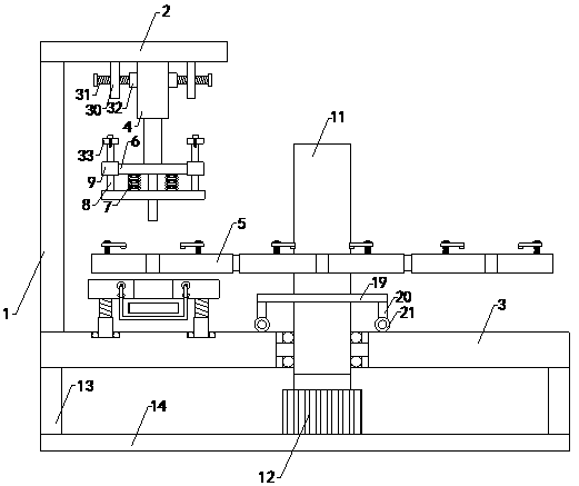
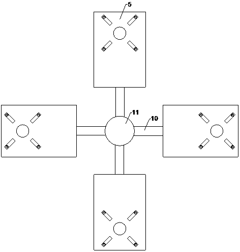
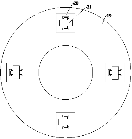
[0023] Such as Figure 1 to Figure 8 As shown, a new energy automobile sheet metal punching device of the present invention includes a support plate 1, a fixed plate 2, an operation plate 3, a hydraulic cylinder 4 and a stamping plate 5, and the bottom end of the support plate and the top end of the operation plate are left side connection, and the bottom left side of the fixed plate is connected with the top end of the support plate, the top of the hydraulic cylinder is connected with the bottom right side of the fixed plate, and the bottom end of the telescopic rod inside the hydraulic cylinder is provided with a stamping head, and the stamping plate is set on The top of ...


PUM


Abstract

The invention relates to the technical field of new energy automobile sheet metal part machining accessory devices, in particular to a punching device of a novel energy automobile sheet metal part. Apunching head is capable of conveniently separating from the sheet metal part after punching is finished, and the practicability is improved; meanwhile, a plurality of groups of sheet metal parts canbe subjected to continuous punching operation by the punching device, and the use limitation is reduced; the placement stability of the sheet metal part is improved, the deviation is prevented, the position accuracy of a punching position is improved, and the use reliability is improved; the punching device comprise a supporting plate, a fixing plate, an operating plate, a hydraulic cylinder and punching plates; the punching device comprises an upper top plate, a lower top plate, four groups of supporting springs, two groups of left limiting guide columns, two groups of right limiting guide columns, two groups of left limiting guide sleeves and two groups of right limiting guide sleeves; and the punching device further comprises four groups of connecting rods, a rotating shaft, a steppingmotor, four groups of supporting rods and a bottom plate; and clamping devices comprises lead screws, nuts, pressing rods and rigid springs, and the bottom ends of the lead screws are connected with the top ends of punching rods, and mounting through holes penetrating up and down are longitudinally formed inside one sides of the pressing rods.

Description

technical field [0001] The invention relates to the technical field of processing accessory devices for sheet metal parts of new energy vehicles, in particular to a punching device for sheet metal parts of new energy vehicles. Background technique [0002] As we all know, the new energy vehicle sheet metal punching device is an auxiliary device used in the production process of new energy vehicles to punch the sheet metal parts so as to better assemble the sheet metal parts with other parts , which has been widely used in the field of sheet metal parts processing for new energy vehicles; the existing punching device for sheet metal parts of new energy vehicles includes a support plate, a fixed plate, an operating plate, a hydraulic cylinder and a stamping plate, and the The bottom end is connected to the top left side of the operation panel, and the bottom left side of the fixed plate is connected to the top end of the support plate, the top of the hydraulic cylinder is conn...

Claims


Application Information

Patent Timeline
Patent Type & Authority Applications(China)
IPC IPC(8): B21D28/26B21D43/00B21D45/04
CPCB21D28/26B21D43/003B21D45/04
Inventor 方豫王伟光
Owner 山西云度知识产权服务有限公司
Why Eureka
Try Eureka