
Automated feeding and clamping device for pipe fitting machining

A clamping device and processing device technology, which is applied to positioning devices, metal processing equipment, metal processing machinery parts, etc., can solve the problems of large manual clamping and feeding workload, low clamping and positioning accuracy, and low work efficiency. High clamping efficiency, reduced labor, and resource saving effects

Inactive Publication Date: 2018-12-21
芜湖辉林奥远自动化科技有限公司
View PDF6 Cites 0 Cited by
  • Summary
  • Abstract
  • Description
  • Claims
  • Application Information

AI Technical Summary

Problems solved by technology

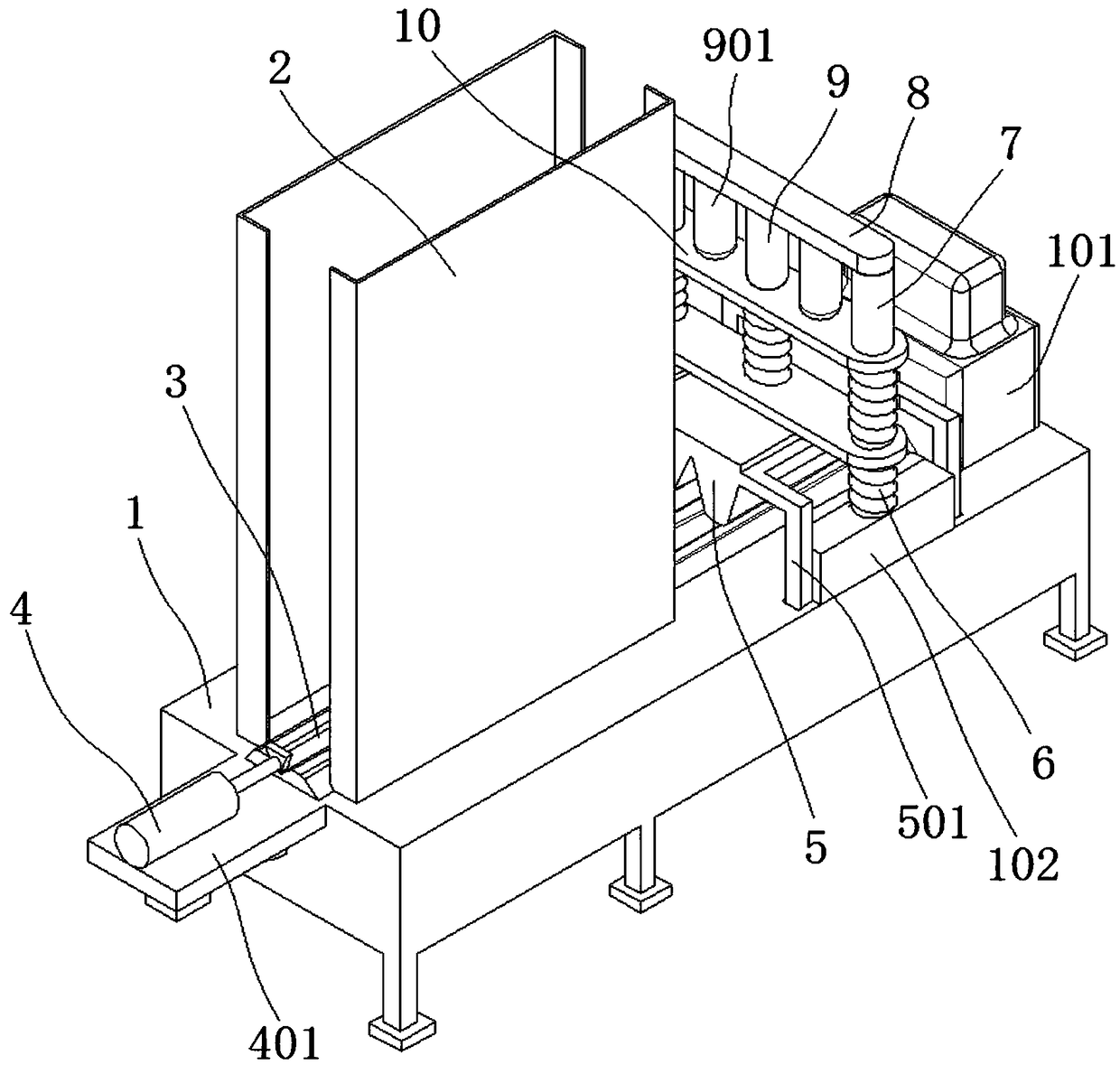
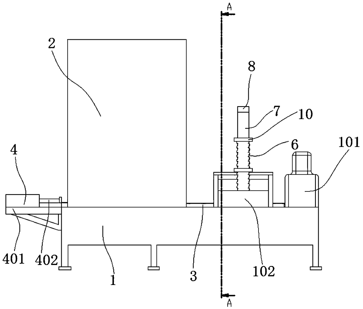
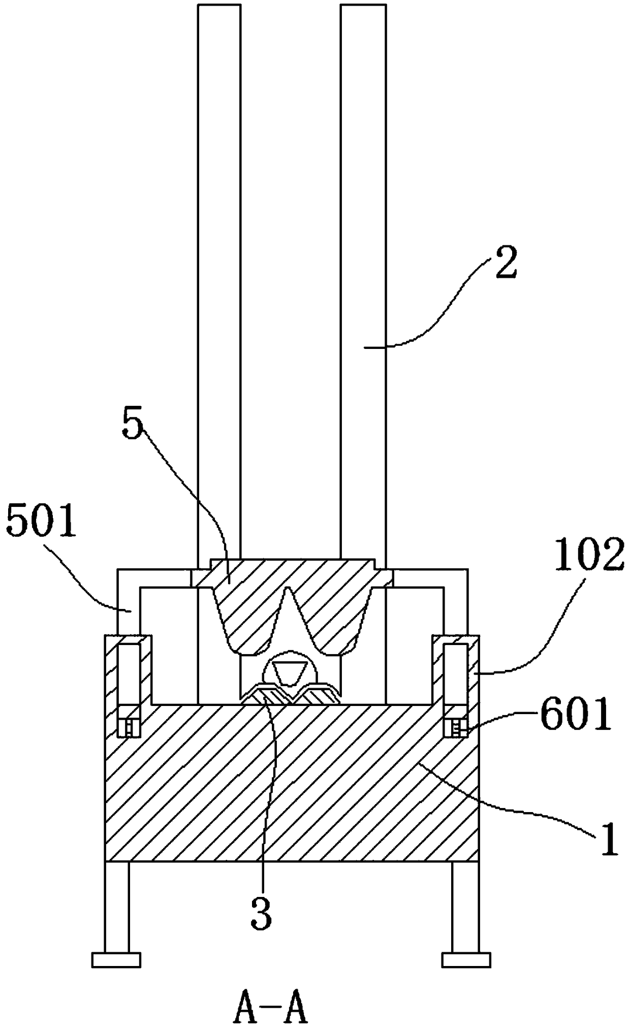
[0004] The object of the present invention is to provide an automatic feeding and clamping device for pipe fittings. By installing guide strips, storage barrels, cylinders, push rods, pressing blocks, and pressing plates on the workbench, the materials to be processed are put into the storage In the barrel, the material is fed by pushing the push rod, and the material is compressed by the pressing block, which solves the problem of low clamping and positioning accuracy of the existing copper tube processing device, large workload of manual clamping and feeding, low work efficiency and resource constraints. waste problem

Method used


Image

  • Automated feeding and clamping device for pipe fitting machining
  • Automated feeding and clamping device for pipe fitting machining
  • Automated feeding and clamping device for pipe fitting machining

Examples


Embodiment Construction

[0032] The following will clearly and completely describe the technical solutions in the embodiments of the present invention with reference to the accompanying drawings in the embodiments of the present invention. Obviously, the described embodiments are only some, not all, embodiments of the present invention. Based on the embodiments of the present invention, all other embodiments obtained by persons of ordinary skill in the art without creative efforts fall within the protection scope of the present invention.

[0033] In the description of the present invention, it should be understood that the terms "open", "upper", "lower", "a pair of sides", "a surface", "end side", "between", "inside", "Corner" and other indications of orientation or positional relationship are only for the convenience of describing the present invention and simplifying the description, rather than indicating or implying that the components or elements referred to must have a specific orientation, be c...


PUM


Abstract

The invention discloses an automated feeding and clamping device for pipe fitting machining, and relates to the technical field of copper pipe machining. The automated feeding and clamping device forpipe fitting machining comprises a workbench; a guiding strip is fixed to the workbench, and fixing blocks are fixed to the opposite sides of the workbench; a storing cylinder and an air cylinder arefixed to one surface of the workbench; a pressing block is slidably arranged on the workbench; and a guiding column is fixed to each fixing block, a cross beam is fixed to the ends of the guiding columns, and two pressing plates are connected to the guiding columns in a sleeving mode. According to the automated feeding and clamping device for pipe fitting machining, to-be-machined materials are put into the storing cylinder, the materials are pushed by a pushing rod for feeding, a to-be-machined workpiece is pressed by the pressing block, therefore, the working efficiency and the clamping andpositioning precision are improved, the production cost is reduced, damage to a red copper pipe in the machining process is reduced, the condition that longitudinal cracks are generated in the red copper pipe machining process is effectively avoided, the leakage probability in the using process is decreased, and environmental pollution is reduced.

Description

technical field [0001] The invention belongs to the technical field of copper pipe processing, in particular to an automatic feeding and clamping device for processing pipe fittings. Background technique [0002] Copper pipe is a kind of non-ferrous metal pipe. The pressed and drawn seamless pipe has the characteristics of firmness and corrosion resistance. Compared with ordinary plastic pipes, it can be found that the main material of plastic pipes contains plasticizers. Chemical additives, such as chemical additives, are easy to cause escape or hardening and embrittlement of plastics with time and temperature changes. The copper copper tube does not have various modifiers, additives, additives and other chemical components of the plastic tube, and its properties are very stable. Moreover, E. coli in the water supply cannot continue to multiply in the copper pipe, and the tissue structure of the copper pipe is extremely dense and impermeable. Harmful substances such as gr...

Claims


Application Information

Patent Timeline
Patent Type & Authority Applications(China)
IPC IPC(8): B23Q3/08
CPCB23Q3/082
Inventor 王根淼
Owner 芜湖辉林奥远自动化科技有限公司
Learn More