Concrete hollow slab bridge with horizontal reinforced bridge deck pavement layer

A bridge deck pavement and hollow slab bridge technology, which is applied in bridges, bridge parts, bridge construction, etc., can solve problems affecting the normal use of hollow slab bridges, bridge transverse force transmission performance decline, and bridge deck longitudinal cracks along hinge joints, etc. , to achieve the effect of easy construction quality, obvious reinforcement effect and avoiding longitudinal cracks

Active Publication Date: 2017-07-28
CHONGQING TECH & BUSINESS INST
View PDF8 Cites 3 Cited by
  • Summary
  • Abstract
  • Description
  • Claims
  • Application Information

AI Technical Summary

Problems solved by technology

[0002] Concrete hollow slab bridge is a bridge with multiple hollow slab longitudinal girders along the bridge direction to form a spanning structure. It has the advantages of convenient construction, low engineering cost, standardized and centralized prefabricated production, and small building height. Concrete hollow slab bridges with transversely reinforced deck pavement are prone to varying degrees of functional and structural damage, such as hinged concrete defects, broken, and long-segment shedding. Improper construction methods, the actual width of the hinge joint between the hollow slab girders is much larger than the designed width of the hinge joint, after a period of operation, the hinge joint is prone to disease, resulting in the decline of the bridge's lateral force transmission performance, making the bridge deck prone to appear along the hinge joint. Longitudinal cracks affect the normal use of hollow slab bridges, and in severe cases, board-by-board damage may occur due to the stress of the single board

Method used


Image

  • Concrete hollow slab bridge with horizontal reinforced bridge deck pavement layer
  • Concrete hollow slab bridge with horizontal reinforced bridge deck pavement layer

Examples


Embodiment Construction

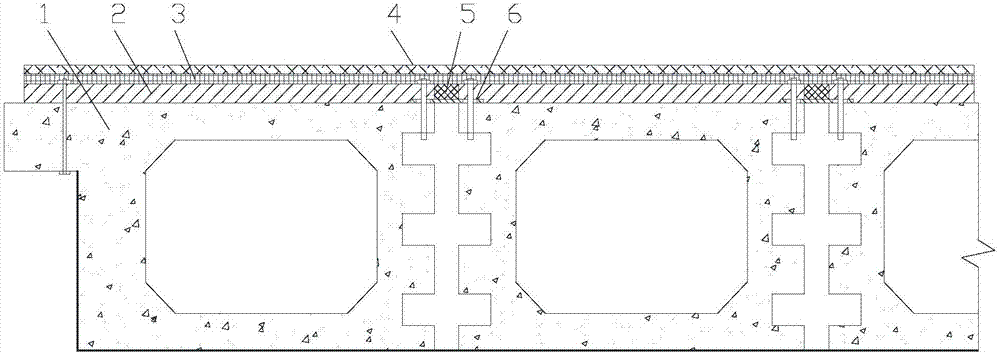
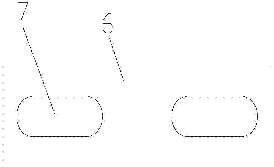
[0016] figure 1 It is a schematic diagram of the structure of the present invention, as shown in the figure: the concrete hollow slab bridge with transversely reinforced bridge deck pavement in this embodiment includes a bridge deck beam formed by a plurality of hollow slab girders arranged side by side and arranged on the The transversely reinforced pavement layer on the top surface of the bridge deck beam; the transversely reinforced pavement layer includes a multi-section steel plate 2 correspondingly laid on the hollow plate girder, a sliding layer 4 supported on the steel plate 2 and The asphalt layer laid on the sliding layer 4; the steel plates 2 and the corresponding bridge deck beams are fixed to each other, and two adjacent steel plates 2 are connected by connectors to transmit lateral loads. In this embodiment The transverse load between the hollow slab girders of the hollow slab bridge can be transmitted through the connectors between the steel plates 2, the overal...


PUM


Abstract

The invention discloses a concrete hollow slab bridge with a horizontal reinforced bridge deck pavement layer. The concrete hollow slab bridge comprises bridge deck beams and a horizontal reinforced pavement layer, wherein the bridge deck beams are composed of multiple hollow slab beams arranged in parallel, and the horizontal reinforced pavement layer is arranged on the top surfaces of the bridge deck beams. The horizontal reinforced pavement layer comprises a plurality of steel plates laid on the hollow slab beams in a one-to-one correspondence mode, a sliding layer supported by the steel plates and an asphalt layer laid on the sliding layer. The steel plates and the corresponding bridge deck beams are fixed to each other, and lateral load is transmitted through connecting parts between two adjacent steel plates. According to the concrete hollow slab bridge, the strength of the integral structure is high, the bearing capacity of the bridge beam is high, single plate stress can be avoided through reinforcement of horizontal steel beams, the service life of the bridge beam is prolonged, the structure is simple, the construction quality of a project is easy to guarantee, and the stress performance is good.

Description

technical field [0001] The invention relates to a bridge construction, in particular to a concrete hollow slab bridge with a transversely reinforced bridge deck pavement layer. Background technique [0002] Concrete hollow slab bridge is a bridge with multiple hollow slab longitudinal girders along the bridge direction to form a spanning structure. It has the advantages of convenient construction, low engineering cost, standardized centralized prefabrication production, and small building height. Concrete hollow slab bridges with transversely reinforced deck pavement are prone to varying degrees of functional and structural damage, such as hinged concrete defects, broken, and long-segment shedding. Improper construction methods, the actual width of the hinge joint between the hollow slab girders is much larger than the designed width of the hinge joint, after a period of operation, the hinge joint is prone to disease, leading to the decline of the bridge's lateral force tran...

Claims


Application Information

Patent Timeline
Patent Type & Authority Applications(China)
IPC IPC(8): E01D12/00E01D19/12
CPCE01D12/00E01D19/12
Inventor 郝笑甜
Owner CHONGQING TECH & BUSINESS INST
Why Eureka
Try Eureka