
Centering auxiliary clamp for 3R fixture to clamp blank materials

An auxiliary fixture and clamping technology, applied in the direction of clamping, positioning devices, manufacturing tools, etc., can solve the problems that the reference edge of the electrode cannot be processed in place, the blank cannot be clamped accurately, and the electrode is unqualified, etc., to achieve shortening Clamping time, improving the workpiece qualification rate, and improving the effect of clamping efficiency

Pending Publication Date: 2018-12-21
安徽宁国中鼎模具制造有限公司
View PDF0 Cites 3 Cited by
  • Summary
  • Abstract
  • Description
  • Claims
  • Application Information

AI Technical Summary

Problems solved by technology

[0002] The traditional electrode processing is to directly clamp the electrode blanks on the machine tool and then process them according to the number of points. Now, it is basically realized that the small electrode blanks are processed in batches by using fixtures. By using the fixtures to process electrodes in batches, a large The utilization rate of the machine tool has been improved, but a new problem has emerged: many blanks cannot be clamped in the center of the fixture accurately, and there is only 1MM residual material left from the blank to the reference edge, which leads to the inability to process the reference edge of the electrode in place. , resulting in unqualified processed electrodes, which are directly scrapped and need to be re-prepared for processing, resulting in serious waste of resources

Method used


Image

  • Centering auxiliary clamp for 3R fixture to clamp blank materials
  • Centering auxiliary clamp for 3R fixture to clamp blank materials
  • Centering auxiliary clamp for 3R fixture to clamp blank materials

Examples


Embodiment Construction

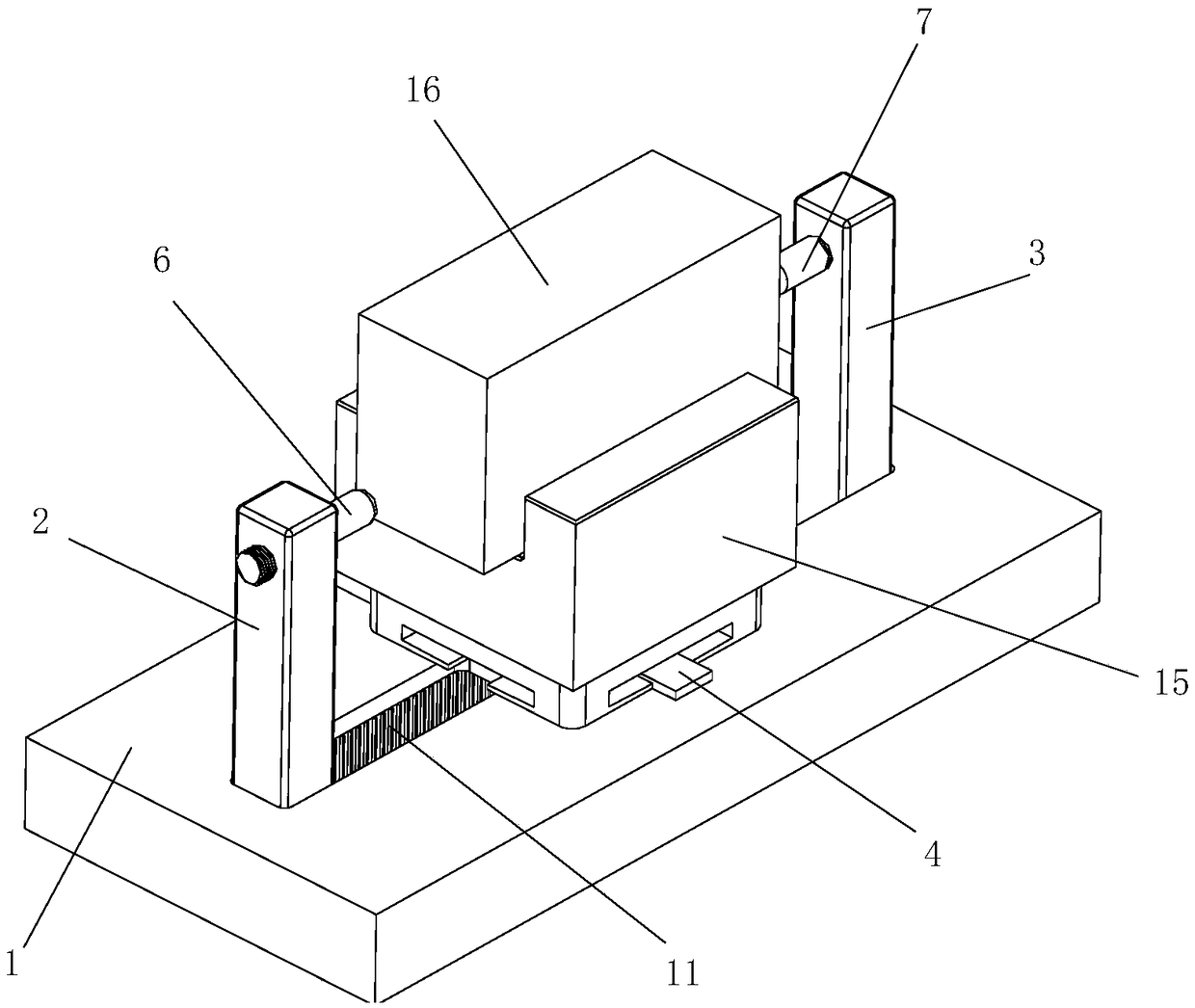
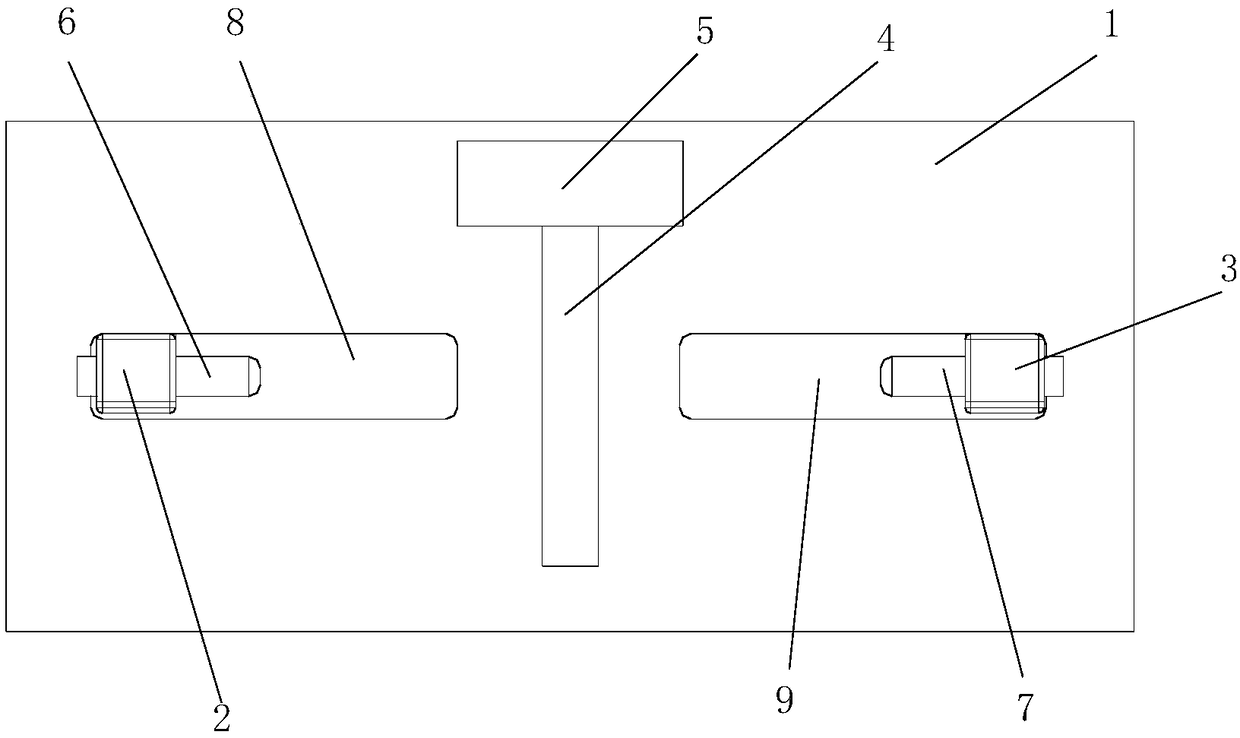
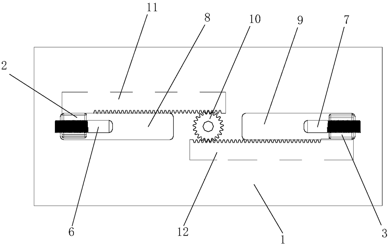
[0015] Such as Figure 1-Figure 5 as shown, figure 1 It is a structural schematic diagram of a centering auxiliary fixture for a 3R fixture for clamping blanks proposed by the present invention; figure 2 It is a top view of a centering auxiliary fixture for a 3R fixture for clamping blanks proposed by the present invention; image 3 It is a structural schematic diagram of the driver in the centering auxiliary fixture for a 3R fixture for clamping blanks proposed by the present invention; Figure 4 It is a schematic diagram of the assembly of the first rack and the first slide bar in the centering auxiliary fixture for a 3R fixture for clamping blanks proposed by the present invention; Figure 5 It is a schematic diagram of the assembly of the second rack and the second slide bar in the centering auxiliary fixture for a 3R fixture for clamping blanks proposed by the present invention.

[0016] refer to Figure 1-Figure 5 , the present invention proposes a centering auxilia...


PUM


Abstract

The invention provides a centering auxiliary clamp for a 3R fixture to clamp blank materials. The centering auxiliary clamp comprises a base, a first sliding rod, a second sliding rod and a driving part. A first positioning plate is arranged at the top end of the base, one end of the first positioning plate is provided with a second positioning plate connected with the first positioning plate andfixed to the base, and the first positioning plate and the second positioning plate are perpendicular to each other. The first sliding rod and the second sliding rod are both vertically arranged and are arranged symmetrically with respect to the center of the first positioning plate. The distance between the first sliding rod and the second sliding rod is adjustable, a first ejector rod is mountedon the inner side of the top end of the first sliding rod, a second ejector rod is mounted on the inner side of the top end of the second sliding rod, and the distance between the first ejector rod and the first positioning plate is equal to the distance between the second ejector rod and the second positioning plate. The driving part is connected with the first sliding rod and the second slidingrod to be used for driving the first sliding rod and the second sliding rod to move back to back or face to face by the same distance at the same time and the same speed. The centering auxiliary clamp improves the clamping efficiency of the blank materials, shortens the clamping time and improves the percent of pass of workpieces.

Description

technical field [0001] The invention relates to the technical field of fixtures, in particular to a centering auxiliary fixture for clamping blanks by a 3R fixture. Background technique [0002] The traditional electrode processing is to directly clamp the electrode blanks on the machine tool and then process them according to the number of points. Now, it is basically realized that the small electrode blanks are processed in batches by using fixtures. By using the fixtures to process electrodes in batches, a large The utilization rate of the machine tool has been improved, but a new problem has emerged: many blanks cannot be clamped in the center of the fixture accurately, and there is only 1MM residual material left from the blank to the reference edge, which leads to the inability to process the reference edge of the electrode in place. , resulting in unqualified processed electrodes, which are directly scrapped and need to be re-processed, resulting in a serious waste of...

Claims


Application Information

Patent Timeline
IPC IPC(8): B23Q3/10
CPCB23Q3/10
Inventor 杨晓璋曹中峰周杰姜建明叶志刚汪平
Owner 安徽宁国中鼎模具制造有限公司
Features
  • Generate Ideas
  • Intellectual Property
  • Life Sciences
  • Materials
  • Tech Scout
  • Unparalleled Data Quality
  • Higher Quality Content
  • 60% Fewer Hallucinations
Learn More