A robot calibration method based on laser tracker

A technology of laser tracker and calibration method, which is applied to manipulators, program-controlled manipulators, manufacturing tools, etc., and can solve the problems that some D-H parameters cannot be reflected

Active Publication Date: 2021-10-01
SHANGHAI STEP ELECTRIC +1
View PDF7 Cites 1 Cited by
  • Summary
  • Abstract
  • Description
  • Claims
  • Application Information

AI Technical Summary

Problems solved by technology

[0007] The purpose of the embodiment of the present invention is to provide a robot calibration method based on a laser tracker, which overcomes the problem that some D-H parameters cannot be reflected in the modeling of the prior art calibration, so that the D-H parameters of the robot can be fully calibrated, and further improve Robot Calibration Accuracy

Method used


Image

  • A robot calibration method based on laser tracker
  • A robot calibration method based on laser tracker
  • A robot calibration method based on laser tracker

Examples


Embodiment Construction

[0028] In order to make the purpose, technical solutions and advantages of the embodiments of the present invention more clear, various implementation modes of the present invention will be described in detail below in conjunction with the accompanying drawings. However, those of ordinary skill in the art can understand that, in each implementation manner of the present invention, many technical details are provided for readers to better understand the present application. However, even without these technical details and various changes and modifications based on the following implementation modes, the technical solution claimed in this application can also be realized.

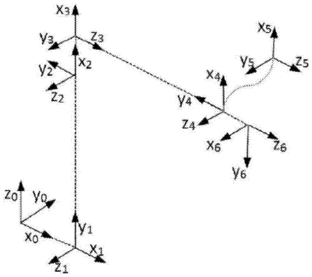
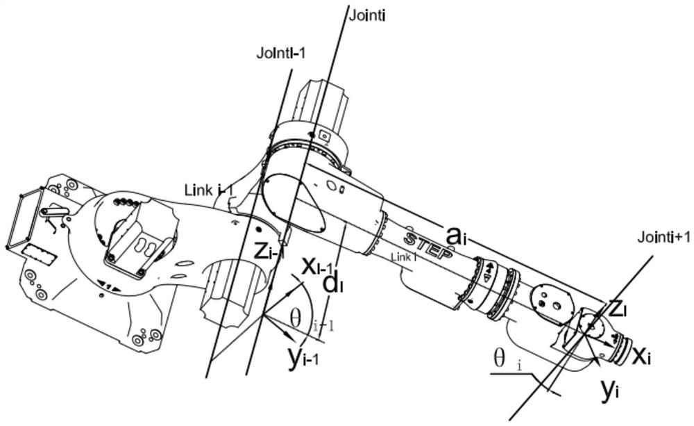
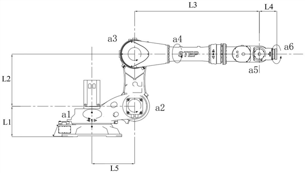
[0029] The first embodiment of the present invention relates to a laser tracker-based robot calibration method, which is suitable for the calibration of industrial robots, such as the calibration of 6-axis robots. This embodiment does not specifically limit the type of robot. The calibration method includes:...


PUM


Abstract

The embodiment of the invention relates to the technical field of industrial robots, and discloses a robot calibration method based on a laser tracker. It includes: sequentially controlling all axes of the robot to perform single-axis rotation, and obtaining the rotation axis J through the laser tracker N Turn E N times, and turn to F each time N The coordinate point group of the center of the target ball at the angle; according to the collected rotation axis J N The coordinate point group of the center of the target ball fits the trajectory circle, and the axis of the trajectory circle is used as the corresponding rotation axis J N The calibration axis equation of each axis of the robot is calculated according to the calibration axis equation of each axis of the robot to obtain the common perpendicular equation of any two adjacent axes in each axis of the robot; the D-H parameter of the robot is calculated according to the calibration axis equation of each axis of the robot and the common vertical line equation ; Calibrate the robot according to the calculated D‑H parameters of the robot. This embodiment overcomes the problem that part of the D-H parameters cannot be reflected in the modeling in the prior art calibration, so that the D-H parameters of the robot can be fully calibrated, and the calibration accuracy of the robot can be further improved.

Description

technical field [0001] The embodiment of the present invention relates to the technical field of industrial robots, in particular to a laser tracker-based robot calibration method. Background technique [0002] With the continuous rise of labor costs, more and more enterprises have begun to automate the transformation of existing production methods. Among them, robots have been widely used in welding, handling, grinding, assembly and other fields due to their flexibility, repeatability, and high precision. [0003] Robot accuracy indicators include repeat positioning accuracy and absolute positioning accuracy. The repeat positioning accuracy is mainly determined by the hardware conditions such as the gear backlash of the reducer and the minimum accuracy of motor control. Generally, it is relatively high, up to 0.02mm or even higher, while the absolute accuracy It is usually lower, and sometimes even reaches the millimeter level, which is unacceptable in welding, grinding, b...

Claims


Application Information

Patent Timeline
Patent Type & Authority Patents(China)
IPC IPC(8): B25J9/04B25J9/16
CPCB25J9/046B25J9/1605
Inventor 李晓华王师石德宇张敏梁邓洪洁
Owner SHANGHAI STEP ELECTRIC
Why Eureka
Try Eureka