
Industrial robot repair and maintenance device

An industrial robot, inspection and maintenance technology, applied in the direction of workbench, manipulator, manufacturing tools, etc., can solve the problems that affect the maintenance work, the area of ​​the inspection platform cannot be changed, and the robot cannot be placed on the platform.

Active Publication Date: 2018-12-21
江苏鼎旭节能建材科技有限公司
View PDF5 Cites 3 Cited by
  • Summary
  • Abstract
  • Description
  • Claims
  • Application Information

AI Technical Summary

Problems solved by technology

[0004] The purpose of the present invention is to provide an industrial robot inspection and maintenance device to solve the problem in the above-mentioned background technology that because the robot is difficult to move, maintenance personnel are required to walk back and forth during maintenance, and the area of ​​the maintenance platform cannot be changed. When the robot being inspected is large in size, the robot cannot be placed on the platform, which affects the maintenance work.

Method used


Image

  • Industrial robot repair and maintenance device
  • Industrial robot repair and maintenance device
  • Industrial robot repair and maintenance device

Examples


Embodiment 1

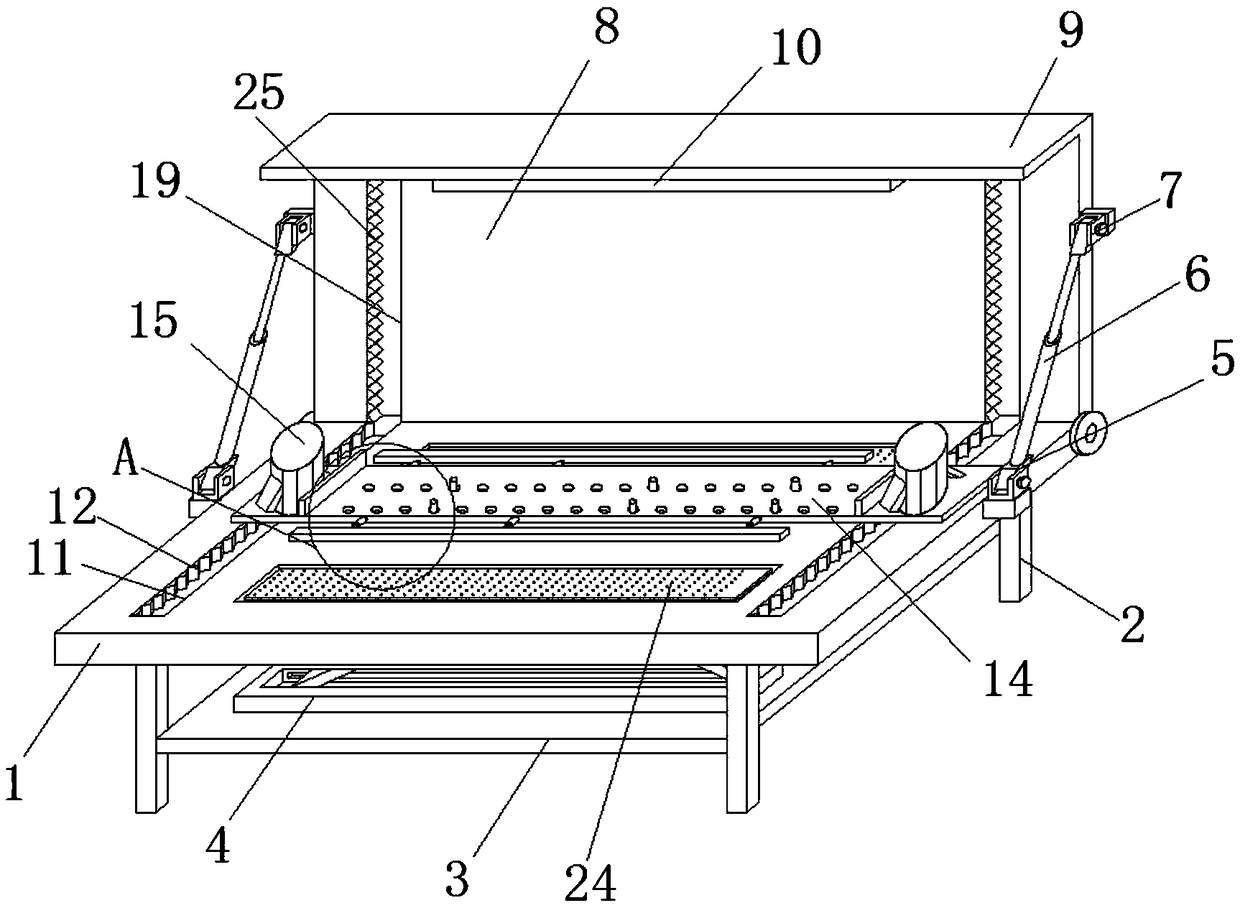
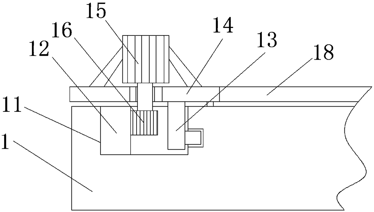
[0022] see Figure 1-4 , this embodiment provides an industrial robot inspection and maintenance device, including an inspection table 1, a support frame 2 is welded to the bottom of the inspection table 1, a mounting plate 3 is fixedly connected to the inner side of the support frame 2, and a scissor is fixedly installed on the top of the mounting plate 3. Type lifting platform 4, scissor lifting platform 4 runs through the maintenance platform 1, both sides of the maintenance platform 1 are fixedly connected with the first hinged seat 5, one side of the first hinged seat 5 is hinged with a hydraulic cylinder 6, and the hydraulic cylinder 6 is far away from the first hinged seat 5. One end of a hinged seat 5 is fixedly connected with a second hinged seat 7, the back of the maintenance platform 1 is hinged with an expansion board 8, and the expansion board 8 is fixedly connected with the second hinged seat 7, and the front of the maintenance platform 1 is provided with a drive ...

Embodiment 2

[0025] see Figure 1-4 , made further improvements on the basis of Embodiment 1: the top of the expansion board 8 is provided with a flange 9, and the bottom of the flange 9 is fixedly connected with a supplementary light 10, under the supplementary light of the supplementary light 10, the maintenance personnel The robot can be observed more clearly to facilitate the maintenance work. The back of the expansion board 8 is provided with a support leg 23, and one side of the support leg 23 is fixedly connected with a shock absorber. When the expansion board 8 is in a horizontal state, the support leg 23 has played a certain supporting role to prevent it from tilting when it bears weight.

[0026]Wherein, the top of scissor lift platform 4 is fixedly connected with anti-skid plate 24, and anti-skid plate 24 is the rubber plate with groove on the surface, has increased the friction between robot and scissor lift platform 4, has played to prevent robot The scissor lift table 4 move...


PUM


Abstract

The invention discloses an industrial robot repair and maintenance device. The industrial robot repair and maintenance device comprises a repair table, a supporting frame is welded to the bottom of the repair table, a mounting plate is fixedly connected to the inner side of the supporting frame, a shear type lifting table is fixedly arranged on the top of the mounting plate, and penetrates throughthe repair table, first hinge bases are fixedly connected to the two sides of the repair table, hydraulic cylinders are hinged to one sides of the first hinge bases, ends, away from the first hinge bases, of the hydraulic cylinders are fixedly connected with second hinge bases, an expansion plate is hinged to the back face of the repair table, and is fixedly connected with the second hinge bases,and a driving groove is formed in the front face of the repair table. The problems that a robot is hard to move, during repair, a repair person needs to walk back and forth, the area of the repair table cannot be changed, when the size of the repaired robot is large, the robot cannot be placed on the table, and repair work is affected are solved.

Description

technical field [0001] The invention relates to the technical field of industrial robots, in particular to an inspection and maintenance device for industrial robots. Background technique [0002] An industrial robot is a multi-joint manipulator or a multi-degree-of-freedom machine device for the industrial field. It can perform work automatically. It is a machine that realizes various functions by its own power and control capabilities. It can accept human commands or follow instructions Running pre-programmed programs, modern industrial robots can also act according to the principles and programs formulated by artificial intelligence technology. [0003] In the process of industrial production, the robot needs to be maintained regularly. When the robot breaks down, it needs to be repaired. Therefore, it is necessary to use a repair platform. Most of the existing repair platforms are composed of ordinary platforms. Most of the robots are Place it directly on the belt platf...

Claims


Application Information

Patent Timeline
Patent Type & Authority Applications(China)
IPC IPC(8): B25J19/00B25H1/16B25H1/14
CPCB25H1/14B25H1/16B25J19/00B25J19/0066
Inventor 吴艳
Owner 江苏鼎旭节能建材科技有限公司
Learn More