A linear control system for a vehicle light assembly that combines taillight functions

A linear control, vehicle technology, applied in the direction of vehicle components, optical signals, the use of semiconductor lights, etc.

Active Publication Date: 2018-12-21
宁波市富来电子科技有限公司
View PDF13 Cites 1 Cited by
  • Summary
  • Abstract
  • Description
  • Claims
  • Application Information

AI Technical Summary

Problems solved by technology

However, because the brake light function needs to indicate to vehicles behind that the vehicle is braking, the brake light function requires a high light output that can be seen

Method used


Image

  • A linear control system for a vehicle light assembly that combines taillight functions

Examples


Embodiment 1

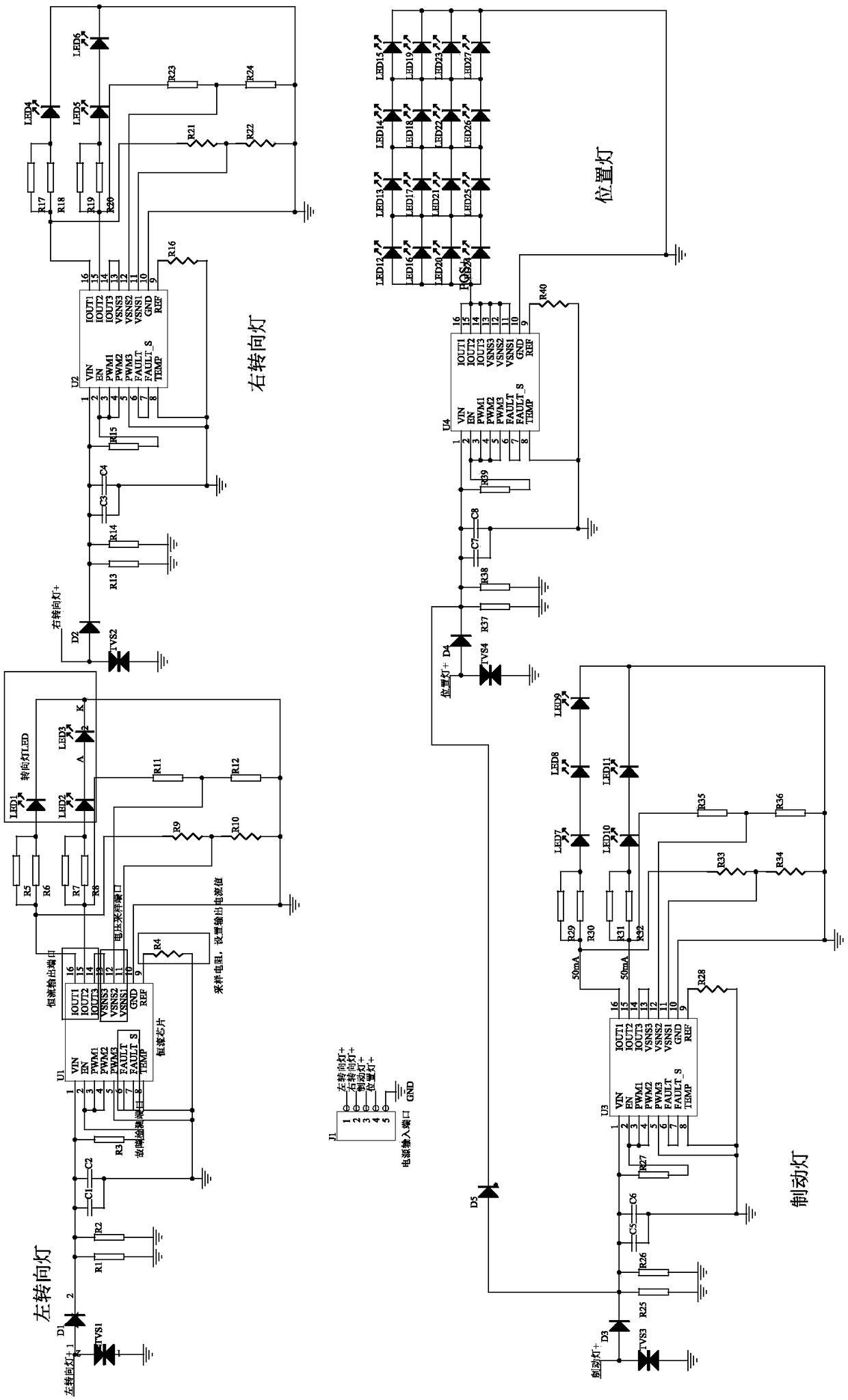
[0022] This embodiment discloses a linear control system for a vehicle lighting assembly for combined taillight functions, the circuit diagram of which is as follows figure 1 As shown, including left turn signal circuit, right turn signal circuit, position light circuit 13 and brake light circuit:

[0023]The right turn signal circuit 11 outputs a constant current to drive the LED to emit light through the first driver chip U1, the left turn signal circuit 12 outputs a constant current to drive the LED to emit light through the second drive chip U2, and the brake light circuit 13 passes The third driver chip U3 outputs a constant current to drive the LED to emit light, and the position light circuit 14 outputs a constant current to drive the LED to emit light through the fourth driver chip U4.

[0024] In this embodiment, when entering the right turn signal / left turn signal mode, the power supply input 13.5V voltage will output a constant current through the driver chip IC to ...


PUM


Abstract

The invention discloses a linear control system for a vehicle light assembly that combines taillight functions, including a left turn light circuit, Right Turn Lamp Circuit, Position Lamp Circuit andBrake Lamp Circuit: the right turn signal lamp circuit outputs a constant current to drive the LED to emit light through the first driving chip U1, The left turn lamp circuit outputs a constant current to drive the LED to emit light through the second driving chip U2, the brake lamp circuit outputs a constant current to drive the LED to emit light through the third driving chip U3, and the position lamp circuit outputs a constant current to drive the LED to emit light through the fourth driving chip U4. The left / right turn signal lamp, position lamp and brake lamp of the vehicle lamp are controlled to emit light by the driving chip, so as to meet the high light output of the night running lamp of the daytime running lamp; Simultaneously has the fault detection function, when the position lamp single malfunction, the entire position lamp normal work, satisfies the position lamp output effect, but when the turn signal lamp / position lamp single LED malfunction, the entire turn signal lamp / position lamp does not output.

Description

technical field [0001] The invention relates to the technical field of automotive electronics, in particular to a linear control system for a vehicle lighting assembly for combining taillight functions Background technique [0002] Car tail lights are lights mounted on the rear of a vehicle, usually with a red body color. It mainly refers to the red brake light (width indicator light) behind the car used as a warning to the trailing vehicle; the amber turn signal that acts as a direction indicator; the brake light that indicates to other road users behind the vehicle that the vehicle is braking. There are one turn signal on the left and one on the left. When the vehicle is turning, the blinking indicator light in the corresponding direction is turned on to warn pedestrians or vehicles in front of or behind the vehicle, and prompt the driving direction of the vehicle. The position marker light function provides light that makes your vehicle visible to vehicles behind you in ...

Claims


Application Information

Patent Timeline
Patent Type & Authority Applications(China)
IPC IPC(8): B60Q1/30B60Q1/34B60Q1/44B60Q11/00
CPCB60Q1/30B60Q1/34B60Q1/44B60Q11/00Y02B20/30
Inventor 党晓东钟健高社科刘玲盛道学
Owner 宁波市富来电子科技有限公司
Why Eureka
Try Eureka