
A microwave de-icing device for aircraft

A microwave and aircraft technology, applied in the field of aircraft microwave deicing devices, can solve the problems of low heating efficiency, unsatisfactory heating effect, scattered wave absorbing material distribution, etc., and achieve the effects of fast heating speed, high heat conversion efficiency and high efficiency

Active Publication Date: 2018-12-21
CHINA ELECTRONIC TECH GRP CORP NO 38 RES INST
View PDF6 Cites 3 Cited by
  • Summary
  • Abstract
  • Description
  • Claims
  • Application Information

AI Technical Summary

Problems solved by technology

This microwave deicing method belongs to the radiation field microwave heating method. Because the distribution of the absorbing material is loose in this method, the heating efficiency is low and the heating effect is not ideal.

Method used


Image

  • A microwave de-icing device for aircraft
  • A microwave de-icing device for aircraft
  • A microwave de-icing device for aircraft

Examples


Embodiment 1

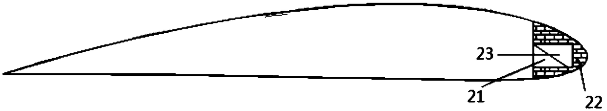
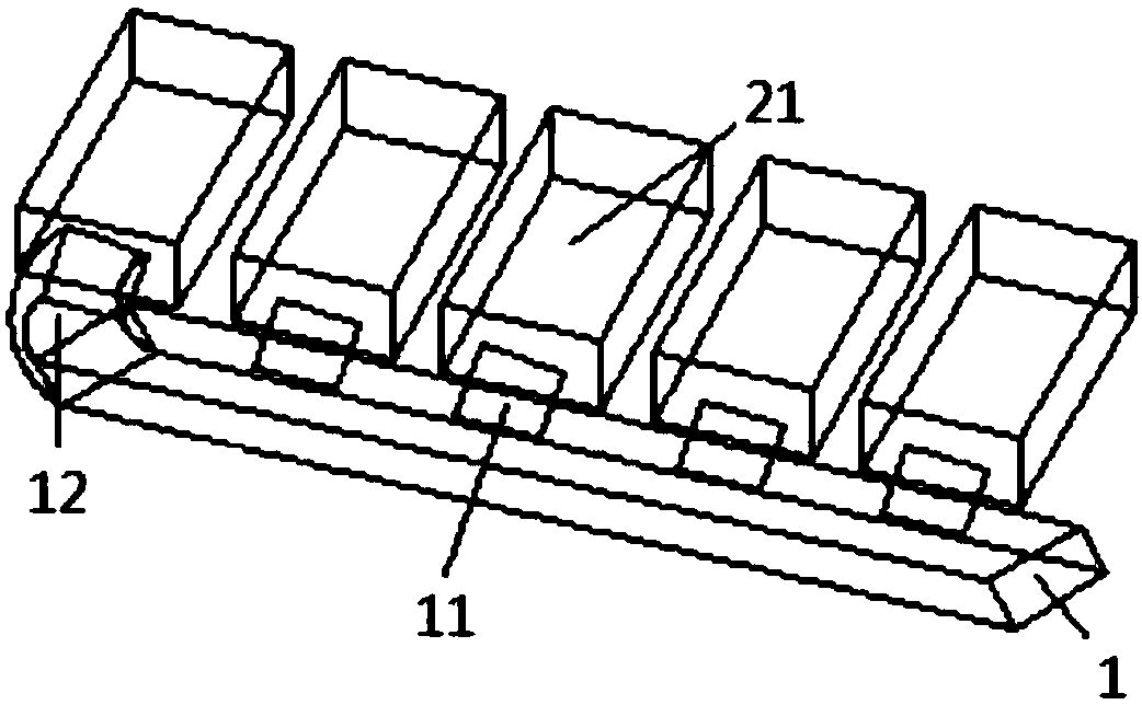
[0040] Such as figure 1 , image 3 , Figure 4 , Figure 5 As shown, the reinforcing ribs 3 of this embodiment are arranged in parallel along the length direction of the wing, and the wave-absorbing load 2 is arranged between adjacent reinforcing ribs 3 on the wing, and each wave-absorbing load 2 includes a waveguide load cavity 21 and The heat dissipation material 22, the heat dissipation material 22 is coated on the periphery of the waveguide load cavity 21, the waveguide absorber 23 is arranged in the waveguide load cavity 21, and the long waveguide 1 passes through the spar 4 of the wing and is coupled to the The microwave input direction of each waveguide loading cavity 21 and each absorbing load 2 is perpendicular to the direction of the long waveguide 1 .

[0041] Because the wedge-shaped wave-absorbing material 24 is installed in the wave-absorbing load 2 , the microwave input into the waveguide load cavity 21 can be matched and absorbed, and the microwave energy is...

Embodiment 2

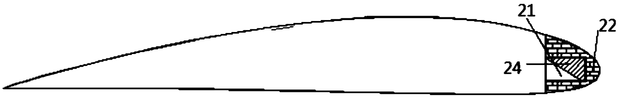
[0049] Such as figure 2 As shown, in this embodiment, when the power of the wave-absorbing load 2 is on the order of tens of watts, a wedge-shaped wave-absorbing material 24 is arranged in the waveguide load cavity 21, and the wave-absorbing material 24 is stacked and filled in a slope shape. The entire rectangular waveguide load cavity 21.

[0050] In Embodiment 1 and Embodiment 2, the microwave reflection coefficients of the two load cavity structures are very small, that is, the impedance matching is achieved, so that all the microwaves input into the load are absorbed by the absorbing material 24, so the heat absorption efficiency is high.

[0051] Other implementations are the same as in Example 1.

[0052] Absorbing material: traditional absorbing materials include ferrite, graphite, etc., and their disadvantage is high density; the absorbing material in this embodiment is carbon fiber, nano material, etc., which has the characteristics of low density.


PUM


Abstract

A microwave de-icing device for aircraft includes a long waveguide and a plurality of microwave absorbing loads disposed between adjacent stiffening ribs of the wing, each absorbing load includes a waveguide load cavity and a heat dissipating material, The heat dissipating material is coated on the periphery of the waveguide load cavity, and the waveguide absorbing sheet or waveguide absorbing material is arranged in the waveguide load cavity. The long waveguide passes through the wing spar of the airfoil and is coupled to each waveguide load cavity through microwave, and the microwave input direction of each microwave absorbing load is perpendicular to the long waveguide direction. According to the characteristics of an aircraft wing, The invention uses the wing to strengthen the space between the wing ribs, and inventions the wing wave absorbing load, because what is used is the matching load, and has the wing structure heat dissipating material can be closely combined with the wingskin, so it has the higher heat conversion efficiency, and adopts the load heating method, and has the advantages of high efficiency, energy saving, high heating speed and the like.

Description

technical field [0001] The invention relates to an aircraft icing treatment technology, in particular to an aircraft microwave deicing device. Background technique [0002] Aircraft icing is an important factor affecting flight safety. Anti-icing work is the key to ensuring air transportation and aviation safety. Currently, the following anti-icing methods are commonly used in civil aviation. [0003] (1) Mechanical anti-icing / de-icing methods [0004] The principle of the mechanical anti-icing method is to break the ice layer by mechanical means, and then blow it off with airflow, or remove the ice by vibration. deicing. [0005] (2) Electric heating anti-icing / deicing method [0006] The principle of the electric heating anti-icing / deicing method is to convert electric energy into thermal energy by energizing the electric heating element to heat the surface of the heated parts of the aircraft for anti-icing / deicing method. [0007] (3) Liquid anti-icing / de-icing method...

Claims


Application Information

Patent Timeline
IPC IPC(8): B64D15/00
CPCB64D15/00
Inventor 吴有恒范鹏荣海春倪勇胡中华胡琦
Owner CHINA ELECTRONIC TECH GRP CORP NO 38 RES INST
Features
  • Generate Ideas
  • Intellectual Property
  • Life Sciences
  • Materials
  • Tech Scout
  • Unparalleled Data Quality
  • Higher Quality Content
  • 60% Fewer Hallucinations
Learn More