Lifting mechanism of section steel palletizing machine and section steel palletizing machine

A stacker and section steel technology, applied in the field of section steel production auxiliary equipment, can solve the problems affecting the output of the hot-rolled section steel production line, the electromagnet lifting mechanism is stuck, and the section steel stacking cannot be completed. Wide range of effects

Pending Publication Date: 2018-12-21
中重科技(天津)股份有限公司
View PDF7 Cites 0 Cited by
  • Summary
  • Abstract
  • Description
  • Claims
  • Application Information

AI Technical Summary

Problems solved by technology

[0003] At present, the palletizing structure of the traversing electromagnet in the section steel rolling line palletizer uses two hydraulic cylinders to control the lifting of the electromagnet. Often, the electromagnet lifting mechanism is stuck due to the asynchrony of the hydraulic cylinders, and the stacking of the section steel cannot be completed. , resulting in low palletizing efficiency and high accident rate, seriously affecting the output of the hot-rolled section steel production line

Method used


Image

  • Lifting mechanism of section steel palletizing machine and section steel palletizing machine
  • Lifting mechanism of section steel palletizing machine and section steel palletizing machine
  • Lifting mechanism of section steel palletizing machine and section steel palletizing machine

Examples


Embodiment Construction

[0027] It should be noted that, in the case of no conflict, the embodiments of the present invention and the features in the embodiments can be combined with each other.

[0028] In describing the present invention, it should be understood that the terms "center", "longitudinal", "transverse", "upper", "lower", "front", "rear", "left", "right", The orientations or positional relationships indicated by "vertical", "horizontal", "top", "bottom", "inner", "outer", etc. are based on the orientation or positional relationships shown in the drawings, and are only for the convenience of describing the present invention Creation and simplification of description, rather than indicating or implying that the device or element referred to must have a specific orientation, be constructed and operate in a specific orientation, and therefore should not be construed as limiting the invention. In addition, the terms "first", "second", etc. are used for descriptive purposes only, and should no...


PUM


Abstract

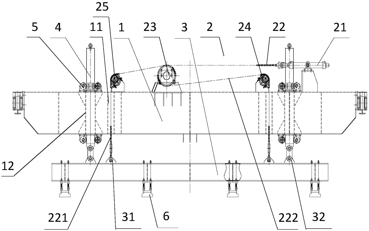
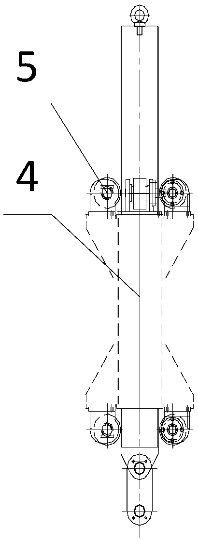
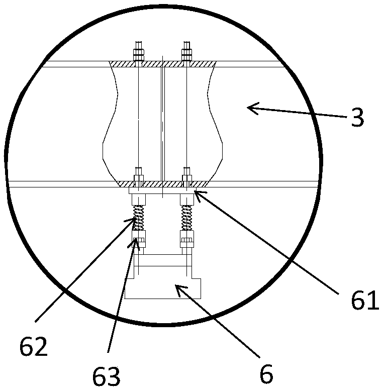
The invention provides a lifting mechanism of a section steel palletizing machine and the section steel palletizing machine. The lifting mechanism of the section steel palletizing machine comprises afirst cross-beam and a second cross-beam. The second cross-beam is fixedly arranged on the lower portion of the first cross-beam through a lifting device, and the lifting device comprises a hydrauliccylinder, and the hydraulic cylinder is fixed to one end of the top surface of the first cross-beam, a separation chain wheel is arranged in the middle of the first cross-beam, one end of a double-rowchain is connected to the output end of the hydraulic cylinder, and the double-row chain is divided into a first chain and a second chain after bypassing the separation sprocket, a first chain wheeland a second chain wheel are separately disposed on two sides of the separation chain wheel, the first chain bypasses the first chain wheel, and the end of the first chain penetrates through the firstcross-beam and is hinged to the second cross-beam. The second chain bypasses the second chain wheel, and the end of the second chain penetrates through the first cross-beam and is hinged to the second cross-beam. A plurality of electromagnets capable of attracting the section steel are uniformly disposed on the bottom surface of the second cross-beam in the length direction. The lifting mechanismachieves the lifting and lowering of the electromagnets by the method that the chains and the chain wheels are driven through the hydraulic cylinder, and the synchronization is greatly improved

Description

technical field [0001] The invention belongs to the field of auxiliary equipment for section steel production, and in particular relates to a lifting mechanism of a section steel palletizer and a section steel palletizer. Background technique [0002] As a new type of steel for building structures, hot-rolled H-shaped steel has the advantages of large section modulus, light weight, metal saving, strong bearing capacity, superior mechanical properties, more beautiful appearance than I-shaped steel, and easy construction, which can lighten the building structure. 30-40% by weight. According to the requirements of the "Outline for the Modernization of the Construction Industry", by 2020, prefabricated buildings will account for more than 20% of new buildings, and hot-rolled H-beams are green products that are encouraged to be used. [0003] At present, two hydraulic cylinders are used to control the lifting of the electromagnet in the palletizing structure of the traversing el...

Claims


Application Information

Patent Timeline
Patent Type & Authority Applications(China)
IPC IPC(8): B65G57/00
CPCB65G57/00
Inventor 毛志森
Owner 中重科技(天津)股份有限公司
Why Eureka
Try Eureka