
Silk yarn winding roller for textile machinery

A technology for textile machinery and winding rollers, which is applied to the field of yarn winding rollers for textile machinery, can solve the problems of inconsistent rotation of the rollers, easy to increase the pulling force, and chaos in the winding of the yarn, and achieve the effect of preventing snapping.

Inactive Publication Date: 2018-12-21
湖州丰硕纺织有限公司
View PDF0 Cites 2 Cited by
  • Summary
  • Abstract
  • Description
  • Claims
  • Application Information

AI Technical Summary

Problems solved by technology

[0005] Aiming at the deficiencies in the prior art, the object of the present invention is to provide a thread winding roller for textile machinery to solve the problem in the prior art that when the thread is wound and concentrated, it is necessary to use a thread roller to allow the winding roller to rotate after being connected to the cylinder. Pull the thread, and it is difficult for the drum to rotate synchronously when the roller rotates, so that the rotation of the drum and roller is inconsistent, causing confusion and interweaving of the wire winding, and then forming knots and clumps, which affect the operation of the textile machine. Synchronous rotation of the control roller When stopping, due to the high inertial rotation speed, it is easy to increase the pulling force when pulling and pulling the silk thread because the other side stops conveying, so that the thread cannot withstand the pulling force and breaks

Method used


Image

  • Silk yarn winding roller for textile machinery
  • Silk yarn winding roller for textile machinery
  • Silk yarn winding roller for textile machinery

Examples


Embodiment Construction

[0026] In order to make the technical means, creative features, goals and effects achieved by the present invention easy to understand, the present invention will be further described below in conjunction with specific embodiments.

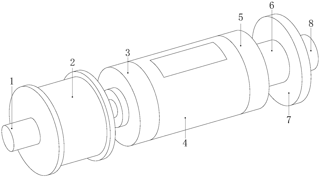
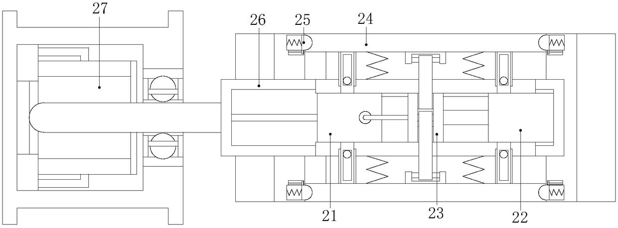
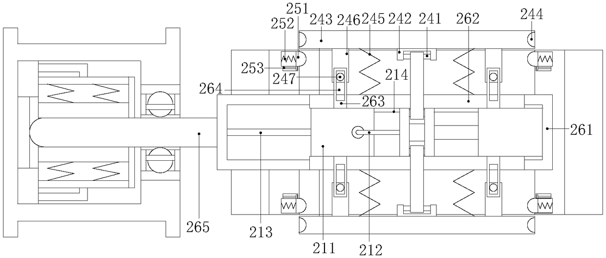
[0027] Such as Figure 1-Figure 6 As shown, the present invention provides a kind of technical scheme of silk winding roller for textile machinery:

[0028] A thread winding roller for textile machinery, the structure of which includes a fixed installation rod 1, a controllable deceleration winding roller internal device 2, a left protection block 3, a winding roller body 4, a right tap protection block 5, a power belt connecting rod 6, Anti-slip disk 7, connecting mounting block 8, the right side of the fixed mounting rod 1 is connected with the left side of the winding roller internal device 2 with controllable deceleration by electric welding and the axis center of the fixed mounting rod 1 is connected with the controllable decelerating The le...


PUM


Abstract

The invention discloses a silk yarn winding roller for textile machinery. The silk yarn winding roller for textile machinery structurally comprises a fixed mounting rod, a winding roller internal device capable of controlling the deceleration, a left protection block, a winding roller body, a right separation protection block, a power strip connecting rod, an anti-skid plate and a connecting mounting block, wherein the right side of the fixed mounting rod is connected with the left side of the inner device of the winding roller of the controllable speed reducer through an electric welding mode, the axis of the fixed mounting rod is perpendicular to the left side of the inner device of the winding roller of the controllable speed reducer, and the inner device of the winding roller capable of controlling the deceleration is arranged on the left surface and the right surface of the left protection block in a penetrating mode and is in interference fit. According to the silk yarn winding roller for the textile machinery, expanding is carried out from the inner side to tension and fix the cylinder, so that the rotation of the roller cylinder is synchronous and consistent, the phenomenonthat the threads are interwoven and knotted when the threads are wound is avoided, rotation speed caused by inertia during rotation of the roller is controlled by reducing rotation speed through friction, and the silk thread is prevented against breakage caused by tension increase when pulled from a single direction.

Description

technical field [0001] The invention relates to the field of textile machinery, more precisely, it relates to a thread winding roller for textile machinery. Background technique [0002] In textile machinery, natural silk or artificially processed silk is processed and interwoven into mechanical equipment for textile products. With the improvement of social progress, textile machinery reduces the need for manual production and increases production, while the winding rollers required for textile machinery will be Concentrated thread collection reduces workload. But there is following shortcoming in present this textile machinery silk winding roller: [0003] 1. When winding and concentrating the silk thread, it is necessary to use a thread roller to connect the winding roller to the barrel and then rotate to pull the thread. However, it is difficult for the barrel to rotate synchronously when the roller is rotating, which makes the rotation of the barrel roller inconsistent ...

Claims


Application Information

Patent Timeline
Patent Type & Authority Applications(China)
IPC IPC(8): B65H75/04B65H75/18
CPCB65H75/04B65H75/18B65H2701/174B65H2701/31
Inventor 沈慧
Owner 湖州丰硕纺织有限公司
Learn More