Steel wire clamping device and application thereof in heat treatment production of steel wire

A clamping device and steel wire technology, applied in heat treatment furnaces, heat treatment equipment, furnaces, etc., can solve problems that affect the quality of steel wire products, easily burn people, and unsafe operation, so as to reduce the phenomenon of steel wire sparking and reduce the amount of waste products , flexible operation

Inactive Publication Date: 2018-12-21
GUIZHOU WIRE ROPE
1 Cites 0 Cited by

AI-Extracted Technical Summary

Problems solved by technology

[0002] For a long time, there is no professional tool to handle the heat-treated steel wire when running in the heating section, and ordinary forks have been used to pick up the wire. This operation is unsafe and easy to burn people, and sparks often occur in the heating section, resulting in over-burning and...

Abstract

The invention discloses a steel wire clamping device. The front end of the bearing rod is provided with a jaw and the rear end is provided with a handle. A tension spring is provided in the bearing rod. Both ends of the tension spring are respectively connected with the jaw and the handle. A locking buckle is provided on the jaw. In the heat treatment production of steel wire, when the steel wireis running, the handle of the steel wire clamping device can be held with hands at the front roller of the heating section, the jaw is opened to align the tail of the steel wire of the running head. The jaw can hold the steel wire firmly with firm holding of the handle while holding the steel wire. The jaw clamps the tail of the running steel wire and raises the steel wire to prevent the running steel wire from contacting other steel wires which causes sparks to damage the steel wire.

Application Domain

Furnace typesHeat treatment furnaces

Technology Topic

EngineeringHeat treated

Image

  • Steel wire clamping device and application thereof in heat treatment production of steel wire

Examples

  • Experimental program(1)

Example Embodiment

[0017] The steel wire clamping device of the present invention and its application in the production of steel wire heat treatment are described in further detail below with reference to the accompanying drawings:
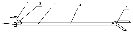
[0018] The steel wire clamping device of the present invention presses figure 1 , It is mainly composed of jaw 1, locking buckle 2, tension spring 3, strut 4 and handle 5; strut 4 is provided with jaw 1 at the front end, handle 5 is provided at the back end, and tension spring is provided in strut 4 3. The two ends of the tension spring 3 are respectively connected with the jaw 1 and the handle 5, and a locking buckle 2 is provided on the jaw 1.
[0019] The jaw 1 is a movable zigzag jaw, and the locking buckle 2 can effectively clamp the steel wire.
[0020] The steel wire clamping device is made of metal materials.
[0021] The steel wire clamping device is made of 304 stainless steel.
[0022] The jaw 1 is made of 304 stainless steel, the support rod 4 is made of 304 stainless steel tube, and the handle 5 is made of plastic or covered with a plastic sleeve.
[0023] The application of the steel wire clamping device of the present invention in the production of steel wire heat treatment. In the production of steel wire heat treatment, when the steel wire is running, hold the handle 5 of the steel wire clamping device by hand at the roller at the front end of the heating section, and the jaw 1 is opened Aim at the wire tail of the running head, hold the handle 5 firmly when clamping the wire, jaw 1 will firmly hold the wire, and jaw 1 will clamp the tail of the running head wire and raise the wire to avoid running head wire Contact with other wires causes sparks to damage the wires.

PUM

no PUM

Description & Claims & Application Information

We can also present the details of the Description, Claims and Application information to help users get a comprehensive understanding of the technical details of the patent, such as background art, summary of invention, brief description of drawings, description of embodiments, and other original content. On the other hand, users can also determine the specific scope of protection of the technology through the list of claims; as well as understand the changes in the life cycle of the technology with the presentation of the patent timeline. Login to view more.

Similar technology patents

Compositions and methods for reducing food intake and controlling weight

InactiveUS20070082107A1reduce caloric intakereduce weight
Owner:MCNEIL NUTRITIONALS

Cooling fan

ActiveUS20100068060A1excellent in strength balancereduce weight
Owner:MITSUBA CORP

New megapixels wide-angle lens

ActiveCN101587232Areduce weightlow cost
Owner:NINGBO SUNNY AUTOMOTIVE OPTECH

Classification and recommendation of technical efficacy words

  • reduce weight

Electrically driven brake booster

InactiveUS20020158510A1reduce weightsimple construction
Owner:BOSCH AUTOMOTIVE SYST CORP

Display device

ActiveUS20140043546A1reduce weightreduce detection sensitivity
Owner:SEMICON ENERGY LAB CO LTD

Curved Automatic-Darkening Filter

InactiveUS20140168546A1reduce weightlow weight
Owner:3M INNOVATIVE PROPERTIES CO

Thermal Solution for Prismatic Lithium Ion Battery Pack

ActiveUS20130115506A1reduce weight
Owner:NEOGRAF SOLUTIONS LLC
Why Eureka
Try Eureka