Variable-diameter reinforcement cage with simple structure and application method

A steel cage and variable diameter technology, which is applied in basic structure engineering, excavation, sheet pile walls, etc., to achieve the effect of concise and reliable structure, good integration, and speeding up the progress and application of the project.

Pending Publication Date: 2018-12-21
安徽俊力建设有限公司
View PDF0 Cites 5 Cited by
  • Summary
  • Abstract
  • Description
  • Claims
  • Application Information

AI Technical Summary

Problems solved by technology

[0020] The object of the present invention is to propose a variable-diameter reinforcement cage with a concise structure and its application method, which can be used for the framework of anti-tension anchor rods, compression-resistant and pull-resistant variable-diameter reinforcement cage expansion piles, that is, adopt the variable-diameter reinforcement with a concise structure The skeleton of the pile with enlarged head at the bottom of the pile composed of cages, the pile bottom of the enlarged head with variable-diameter steel cage skeleton, uses the variable-diameter steel cage, that is, utilizes the steel cage structure, so that the variable-diameter steel cage is released and becomes an enlarged steel cage skeleton Prepare the foundation skeleton of the enlarged head of the pile, which is applied to the preparation of the enlarged head of the head of all the expanded piles, and is integrated with the pile body on the upper part of the expanded pile as much as possible, so as to overcome the shortcomings of the existing pile foundation in terms of solid bearing capacity and poor integrity. and reduce costs

Method used


Image

  • Variable-diameter reinforcement cage with simple structure and application method
  • Variable-diameter reinforcement cage with simple structure and application method
  • Variable-diameter reinforcement cage with simple structure and application method

Examples


Embodiment Construction

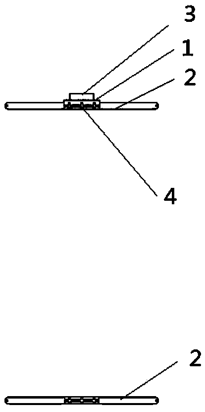
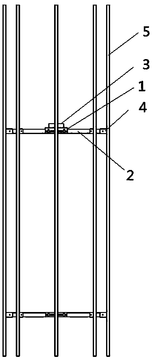
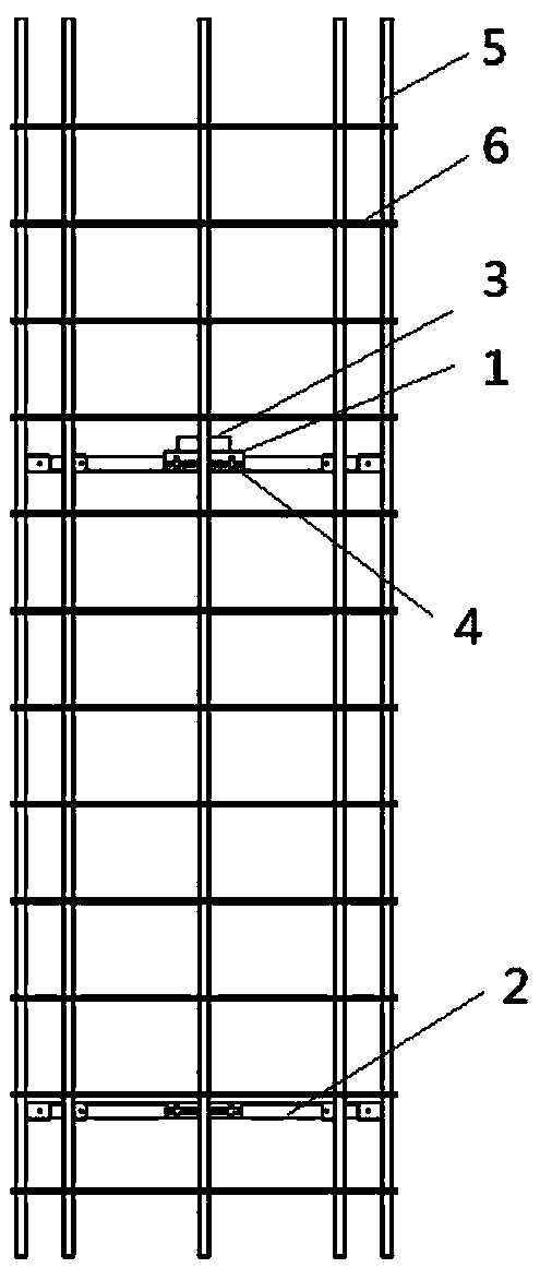
[0065] As shown in the figure, the ring-shaped fixer is the flower part 1, the flexible rib 2, the center hole of the flower part 3, the U-shaped connector 4, the vertical rib 5, the stirrup 6, the steel plate 7, the guide cap 8, the axial Rod 9, spring 11, limit pin 12. Bearing pin hole 4-1, spring is in the ring shape limiter 12-1 of axial rod.

[0066] The main reinforcement of the steel cage is provided, and the ring-shaped fixer (or an axial rod) is set on the main reinforcement of the central shaft hole of the ring-shaped fixer. The displacement action device of the shape fixer: a spring 11 that can be compressed and released is sleeved on the main rib or the axial rod, and the spring is limited by the limiter 12-1 that is sleeved on the axial rod; Pneumatic or hydraulic devices are used to stretch the active ribs connected with the ring-shaped fixer to release the vertical ribs and ring-shaped or spiral-shaped stirrups. The diameter of the main reinforcement can reach...


PUM


Abstract

The invention discloses a variable-diameter reinforcement cage with a simple structure. The variable-diameter reinforcement cage has a variable diameter and comprises a plurality of vertical ribs, a plurality of ring-shaped fixators and a plurality of groups of ribs corresponding to the ring-shaped fixators, wherein one group of ribs, the quantity of which is same as the quantity of the pluralityof vertical ribs, is movably fixed at the outer ring of each ring-shaped fixator; and in each group of ribs, one end of each rib is movably connected with a same-height position of one vertical rib and the other end of each rib is movably connected with the outer ring of one ring-shaped fixator, namely, different heights of each vertical rib are respectively and movably connected with each group of ribs of at least two ring-shaped fixators. The variable-diameter reinforcement cage with the simple structure and an application method can be used for skeletons of compression-resisting and pulling-resisting reinforcement cage expanded bore piles, and are extremely concise and reliable on the structure; through adding a matched releasing device, the cost is reduced to be similar to the cost ofexisting reinforcement cages; and concrete can be directly poured so that the stress effect of the whole pile foundation is better.

Description

technical field [0001] The present invention relates to a variable-diameter reinforcement cage with a concise structure and its application method, which is used for anti-stretch anchor rods, compression-resistant and pull-resistant variable-diameter reinforcement cage expansion piles, especially the skeleton in the pile foundation—a concise structure Variable diameter reinforcement cage. Background technique [0002] As a building foundation pile, it plays a foundation role in building construction. According to the force principle of the foundation, it can be roughly divided into friction piles and bearing piles. [0003] With the continuous development of engineering technology, new steel piles and reinforced concrete piles are used more and more widely in engineering construction. The characteristics of different pile types are also different. [0004] Classified according to bearing properties, friction piles, friction piles--most of the load is borne by the friction ...

Claims


Application Information

Patent Timeline
Patent Type & Authority Applications(China)
IPC IPC(8): E02D5/34E02D5/76E02D17/20
CPCE02D5/34E02D5/76E02D17/207
Inventor 王林陶刚王军
Owner 安徽俊力建设有限公司
Why Eureka
Try Eureka