Grouting pump and connecting structure of plunger and crosshead

A connecting structure and cross-head technology are applied to the components, pumps, and pump elements of a pumping device for elastic fluids, which can solve problems such as increasing labor intensity.

Active Publication Date: 2018-12-21
三川德青工程机械有限公司
View PDF4 Cites 0 Cited by
  • Summary
  • Abstract
  • Description
  • Claims
  • Application Information

AI Technical Summary

Problems solved by technology

The construction site is generally a three-cylinder grouting pump. Every time a plunger is replaced, the heavy hydraulic end needs to be disassembled, which increases the labor intensity.

Method used


Image

  • Grouting pump and connecting structure of plunger and crosshead
  • Grouting pump and connecting structure of plunger and crosshead
  • Grouting pump and connecting structure of plunger and crosshead

Examples


Embodiment 1

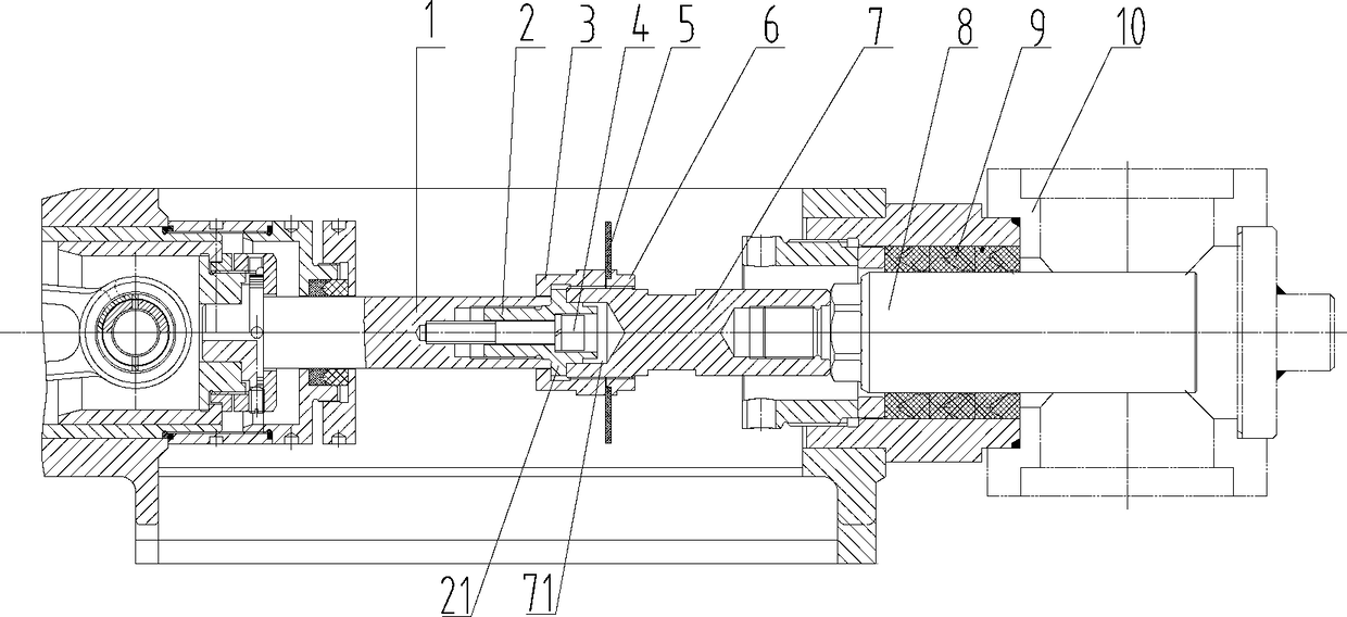
[0026] Such as figure 1 Among them, a connection structure between a plunger and a crosshead of a grouting pump includes a plunger 8 and a crosshead 1, the plunger 8 is connected to the crosshead 1 through a connecting body 7, and the connecting body 7 is a detachable structure. With this structure, it is possible to quickly replace the plunger 8 without disassembling the heavy liquid end, reduce labor intensity, and improve maintenance efficiency.

[0027] The preferred solution is as figure 1 Among them, the crosshead 1 is socketed with the positioning body 2, the outer nut 3 is socketed with the crosshead 1, and is axially limited by the boss 21 of the positioning body 2, the outer nut 3 is threaded with the connecting body 7, and the connecting body 7 is connected with the Plunger 8 threaded connection. With this structure, it is easy to disassemble and improve the coaxial precision between the crosshead 1 and the plunger 8 .

[0028] In a preferred solution, the crossh...

Embodiment 2

[0034] Such as figure 1 Among them, a grouting pump, including a plunger 8, a crosshead 1 for connecting the driving device, the plunger 8 is installed in the cylinder body, the cylinder body is provided with a hydraulic end for liquid inlet and discharge, the plunger 8 is connected to the crosshead 1 through the connecting body 7, and the connecting body 7 is a detachable structure;

[0035] The crosshead 1 is socketed with the positioning body 2, the outer nut 3 is socketed with the crosshead 1, and is axially limited by the boss 21 of the positioning body 2, the outer nut 3 is threaded with the connecting body 7, and the connecting body 7 is connected with the plunger 8 threaded connections.

[0036] In a preferred solution, the crosshead 1 is provided with an internal thread, the positioning body 2 is provided with an external thread, and the crosshead 1 is threadedly connected with the positioning body 2;

[0037] One end of the positioning body 2 is provided with a pos...

Embodiment 3

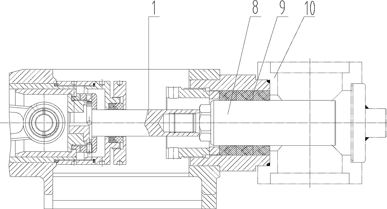
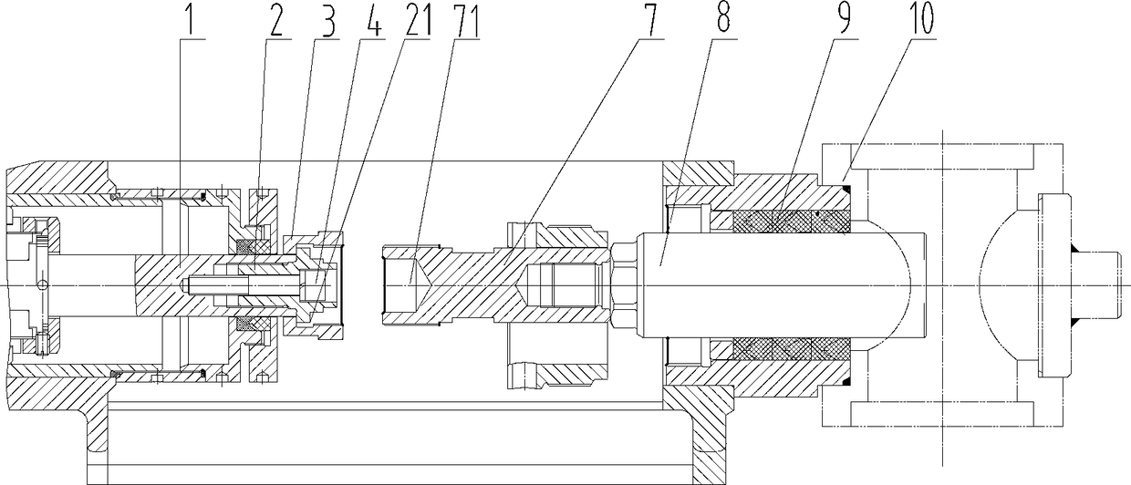
[0043] Plunger removal method attached image 3 , Figure 4 , Turn the crank linkage mechanism of the grouting pump with a tool, the connecting rod drives the crosshead 1 to rotate to the slurry suction position, and loosen the plunger 8 sealing group. Loosen the threaded connection between the locking nut 6 and the outer nut 3 and the connecting body 7, and continue to rotate the crank linkage mechanism so that the connecting rod drives the crosshead 1 to reach the slurry suction limit position. At this time, there is a gap between the connecting body 7 and the positioning body 2 distance. Use a tool to separate the threaded connection between the connecting body 7 and the plunger 8 . Take out the connecting body 7, and finally take out the plunger 8. Putting back the new plunger 8 is a reverse process of disassembly. After the plunger 8 is installed, compress the plunger 8 sealing group.


PUM


Abstract

The invention provides a connecting structure of a plunger and a crosshead of a grouting pump. The connecting structure comprises the plunger and the crosshead, the plunger is connected with the crosshead through a connecting body, and the connecting body is of a detachable structure. In the construction site, a three-cylinder grouting pump is generally used, when one plunger is replaced every time, the heavy hydraulic end needs to be disassembled, so that the labor intensity of workers is additionally increased; and in order to better accelerate the efficiency, the plunger and the crosshead are designed into a detachable mechanism, so that the effects that the heavy hydraulic end is not disassembled, the plunger is rapidly replaced, the labor intensity of the workers is reduced, and the construction efficiency is improved are achieved.

Description

technical field [0001] The invention relates to the field of grouting pump equipment, in particular to a connection structure between a plunger and a crosshead of a grouting pump and the grouting pump. Background technique [0002] Grouting pumps are mainly used in dam foundation engineering, tunnel grouting, and building foundation grouting. As for the plunger that is in direct contact with the slurry, it must be replaced with a new plunger after wear and tear. Generally, it is necessary to manually open the components of the liquid end, loosen the plunger seal assembly, and then separate the connection between the plunger and the crosshead (The connection method is one of plane connection, spherical connection and thread connection). The construction site is generally a three-cylinder grouting pump. Every time a plunger is replaced, the heavy fluid end needs to be disassembled, which increases the labor intensity. Contents of the invention [0003] The invention provid...

Claims


Application Information

Patent Timeline
Patent Type & Authority Applications(China)
IPC IPC(8): F04B15/02F04B53/14
CPCF04B15/02F04B53/14
Inventor 朱科
Owner 三川德青工程机械有限公司
Why Eureka
Try Eureka