An unloading buffer hydraulic system

A hydraulic system and high-pressure technology, which is applied in the field of unloading buffer hydraulic system, can solve the serious problems of water hammer and other problems, and achieve the effects of improving safety, preventing loosening and oil leakage, and reducing strong impact

Active Publication Date: 2020-07-10
FUJIAN LONGMA ENVIRONMENTAL SANITATION EQUIP
View PDF9 Cites 0 Cited by
  • Summary
  • Abstract
  • Description
  • Claims
  • Application Information

AI Technical Summary

Problems solved by technology

[0008] Therefore, it is necessary to provide an unloading buffer hydraulic system to solve the serious problem of water hammer in the hydraulic drive system of the push plate cylinder in the prior art

Method used


Image

  • An unloading buffer hydraulic system

Examples


Embodiment Construction

[0038] In order to explain in detail the technical content, structural features, achieved goals and effects of the technical solution, the following will be described in detail in conjunction with specific embodiments and accompanying drawings.

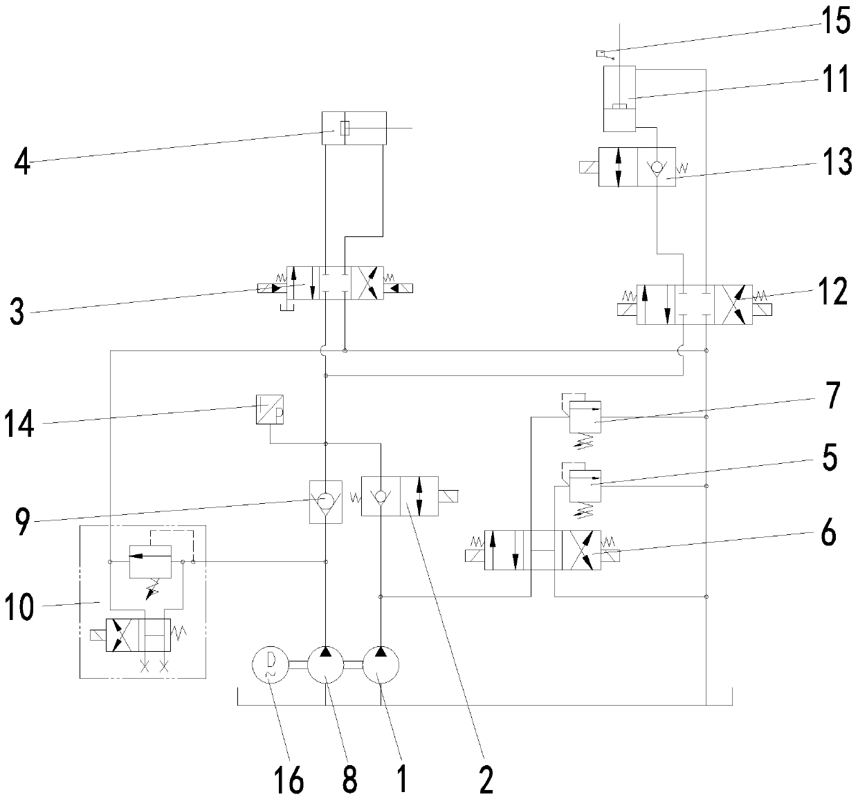
[0039] see figure 1 , the present invention provides an unloading buffer hydraulic system, the system includes a first pump body 1, a first reversing valve 2, a second reversing valve 3, a push plate cylinder 4 and a low pressure relief valve of the first pump body , the first pump body 1 communicates with the hydraulic oil tank and the second reversing valve 3 through the main pressure oil circuit, and the two oil outlets of the second reversing valve 3 are connected with the rod chamber and the rodless chamber of the push plate cylinder 4 respectively. The oil return port of the second reversing valve 3 communicates with the hydraulic oil tank through the oil return line. The first reversing valve 2 is arranged between the first pum...


PUM


Abstract

The invention relates to the technical field of hydraulic control, in particular to an unloading buffer hydraulic system. The system comprises a first pump body, a first reversing valve, a second reversing valve, a pushing plate oil cylinder and a first pump body low-pressure overflow valve; the first pump body is in communication with a hydraulic oil tank and the second reversing valve through amain pressure oil way, two oil outlets of the second reversing valve are connected to a rod cavity and a rodless cavity of the pushing plate oil cylinder respectively, and an oil return port of the second reversing valve is in communication with the hydraulic oil tank through an oil return pipeline; the first reversing valve is arranged between the first pump body and the second reversing valve, one end of the first pump body low-pressure overflow valve is connected to a pipeline between the first pump body and the first reversing valve, and the other end of the first pump body low-pressure overflow valve is in communication with the oil return pipeline; and before the second reversing valve carries out the reversing operation, the high-pressure oil unloading is carried out by the pushingplate oil cylinder. According to the unloading buffer hydraulic system of a rubbish compression box, unloading buffer of the pushing plate oil cylinder can be well achieved, the strong impact problemof a water hammer phenomenon is effectively solved, and the safety of an oil supply pipeline of the pushing plate oil cylinder is greatly improved.

Description

technical field [0001] The invention relates to the technical field of hydraulic control, in particular to an unloading buffer hydraulic system. Background technique [0002] At present, the compression push plate and the loading mode of the loading hopper of the integrated garbage compression box of the domestic garbage compression category all adopt hydraulic control to directly start and stop. [0003] The existing hydraulic drive system has the following problems in use: First, due to the large volume of the push plate cylinder, the extension and retraction of the push plate cylinder are determined by sensing the oil pressure in the main pressure oil circuit, and the pressure is basically 20MPa Left and right, therefore, when the push pedal cylinder is recovering, it will seal a large amount of high-pressure oil between the push pedal cylinder and the reversing valve. When the hydraulic system is directly reversing, the high-pressure oil will directly return to the oil t...

Claims


Application Information

Patent Timeline
Patent Type & Authority Patents(China)
IPC IPC(8): F15B11/08F15B13/04
CPCF15B11/08F15B13/04
Inventor 李基锋张庆明张宗锋巫彬民刘玮
Owner FUJIAN LONGMA ENVIRONMENTAL SANITATION EQUIP
Why Eureka
Try Eureka