Rotating shaft bearing structure and motor

A technology of axial bearing and rotating shaft, applied in the field of rotating shaft bearing structure and motor, can solve the problems of rotating shaft collision, affecting the normal operation of the motor, etc., and achieve the effect of improving reliability

Pending Publication Date: 2018-12-21
GREE ELECTRIC APPLIANCES INC
View PDF0 Cites 6 Cited by
  • Summary
  • Abstract
  • Description
  • Claims
  • Application Information

AI Technical Summary

Problems solved by technology

[0004] Therefore, the technical problem to be solved by the present invention is to overcome the defect that the rotating shaft deviates from the design air gap and collides when the operation of the existing magnetic levitation motor in the prior art is subjected to load impact and instability of the bearing controller, which affects the normal operation of the motor. Thereby providing a rotating shaft bearing structure and motor

Method used


Image

  • Rotating shaft bearing structure and motor
  • Rotating shaft bearing structure and motor
  • Rotating shaft bearing structure and motor

Examples


Embodiment Construction

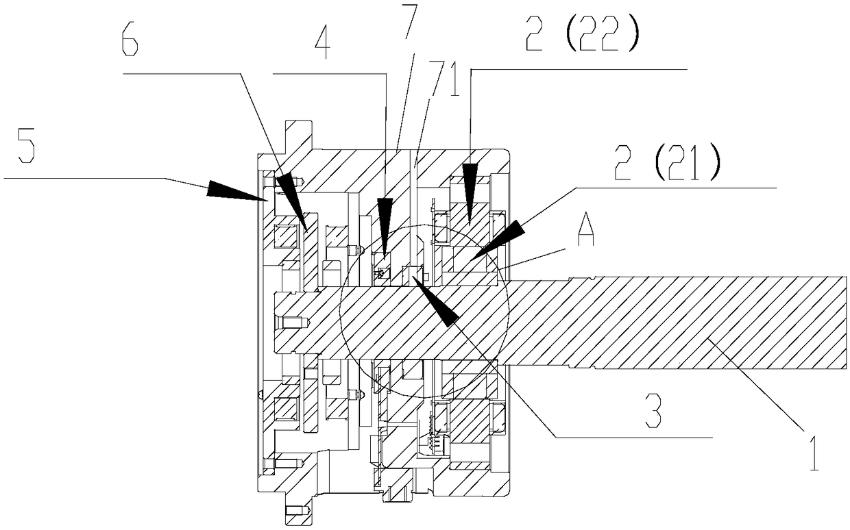
[0036] Such as Figure 1-3 As shown, the present invention provides a rotating shaft bearing structure, which includes:

[0037] Spindle 1;

[0038] The magnetic suspension radial bearing 2 is sleeved on the rotating shaft 1;

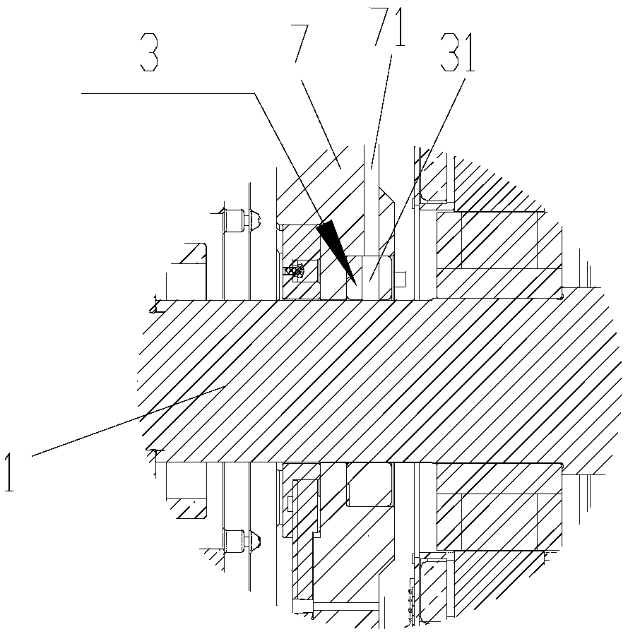
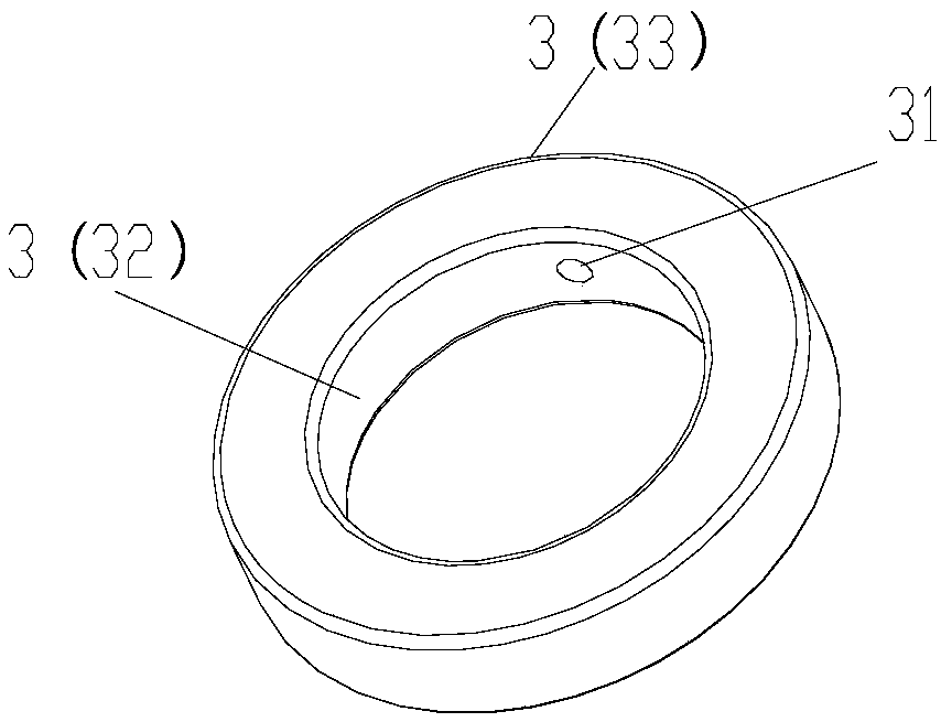
[0039] The static pressure bearing 3 is sleeved on the rotating shaft 1, and the static pressure bearing 3 and the magnetic levitation radial bearing 2 are located at different positions in the axial direction of the rotating shaft 1, and the static pressure bearing 3 A vent hole 31 is provided, one end of the vent hole 31 communicates with the radially inner wall of the hydrostatic bearing, and the other end of the vent hole 31 communicates with the radially outer wall of the hydrostatic bearing 3, so as to be able to The outside of the hydrostatic bearing 3 passes gas with a certain pressure to the gap between the radially inner wall of the hydrostatic bearing 3 and the rotating shaft 1 .

[0040] In the present invention, air holes are provided on...


PUM


Abstract

The invention provides a rotating shaft bearing structure and a motor. The rotating shaft bearing structure comprises a rotating shaft (1), a magnetic suspension radial bearing (2) and a static pressure bearing (3); the magnetic suspension radial bearing (2) sleeves the rotating shaft (1); the static pressure bearing (3) sleeves the rotating shaft (1), and the static pressure bearing (3) and the magnetic suspension radial bearing (2) are located at different positions in the axial direction of the rotating shaft (1); and the static pressure bearing (3) is provided with vent holes (31), one ends of the vent holes (31) are in communication with the radial inner wall of the static pressure bearing, the other ends of the vent holes (31) are in communication with the radial outer wall of the static pressure bearing (3), so that gas with certain pressure is introduced into a gap between the radial inner wall of the static pressure bearing (3) and the rotating shaft (1) from the outside of the static pressure bearing (3). According to the rotating shaft bearing structure, the side, close to the static pressure bearing, of the rotating shaft can bear larger gas pressure, so that the rotating shaft is pressed back into a designed gas gap, so that the rotating shaft is prevented from deviating from the designed gas gap, and the operation reliability of the motor is improved.

Description

technical field [0001] The invention belongs to the technical field of motors, and in particular relates to a rotating shaft bearing structure and a motor. Background technique [0002] At present, the existing high-speed magnetic levitation motor bearing structure is composed of 6 parts, radial bearing stator, radial bearing rotor, axial bearing, thrust plate, sensor and protective ball bearing, wherein the radial bearing rotor is heat-packed on the rotating shaft ;When the motor is at rest, the rotating shaft falls on the protective ball bearing; when the motor is running, the bearing supports the rotating shaft. When the bearing controller is unstable, the rotating shaft deviates from the designed air gap and is prone to collisions, which will damage the protective ball bearings. Too many collisions of the rotating shaft will easily lead to the bending of the rotating shaft, and finally the motor cannot operate normally. [0003] When the existing magnetic levitation mot...

Claims


Application Information

Patent Timeline
Patent Type & Authority Applications(China)
IPC IPC(8): F16C32/04F16C32/06
CPCF16C32/0442F16C32/0662F16C2380/26
Inventor 魏琼刘健宁贾金信张小波李广海郭长光闫瑾李忠雨彭利明梁建东王泽业熊博文
Owner GREE ELECTRIC APPLIANCES INC
Why Eureka
Try Eureka