
Shale gas conveying pipeline

A technology for transporting pipelines and shale gas, which is applied in the direction of pipeline support, pipeline protection, pipeline damage/wear prevention, etc. It can solve problems such as easy cracks on the pipeline wall, cumbersome installation and disassembly, and shale gas leakage, so as to facilitate normal transportation , Reduce the probability of damage and prevent leakage

Inactive Publication Date: 2018-12-21
GUIZHOU UNIV
View PDF10 Cites 4 Cited by
  • Summary
  • Abstract
  • Description
  • Claims
  • Application Information

AI Technical Summary

Problems solved by technology

[0003] However, most of the conveying pipelines currently on the market are spliced ​​through flanges. Although this can play a sealing role, the installation and disassembly are relatively cumbersome. There will still be sloshing phenomenon, and when the air pressure in the pipeline is high, the pipe wall is prone to cracks, which will lead to the leakage of shale gas

Method used


Image

  • Shale gas conveying pipeline
  • Shale gas conveying pipeline
  • Shale gas conveying pipeline

Examples


Embodiment Construction

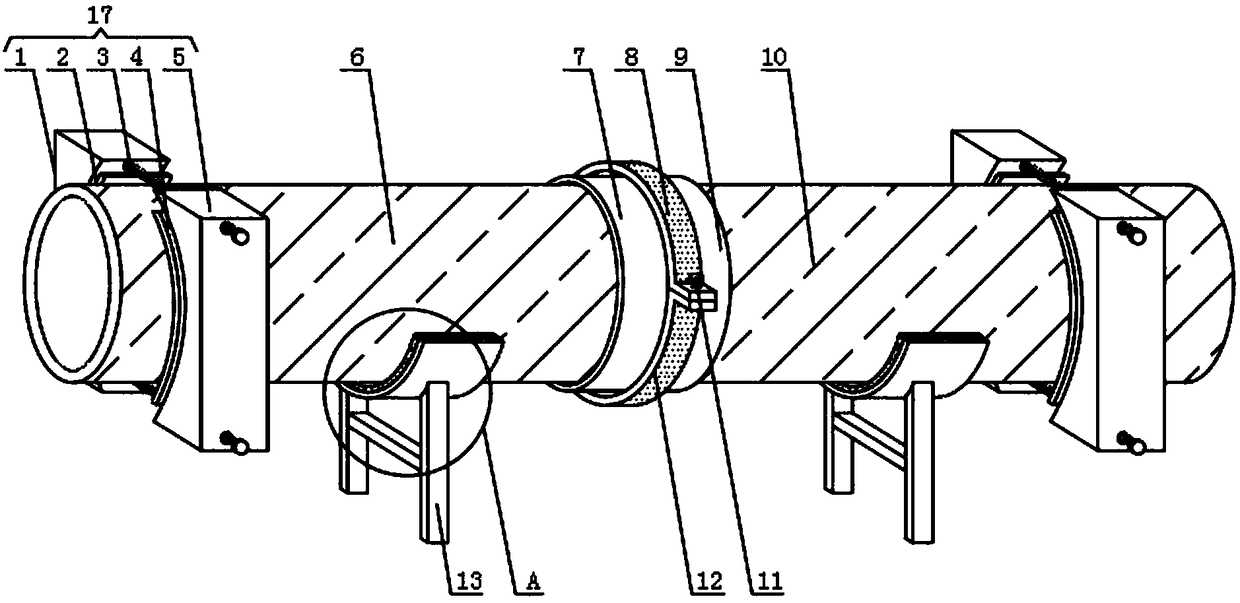
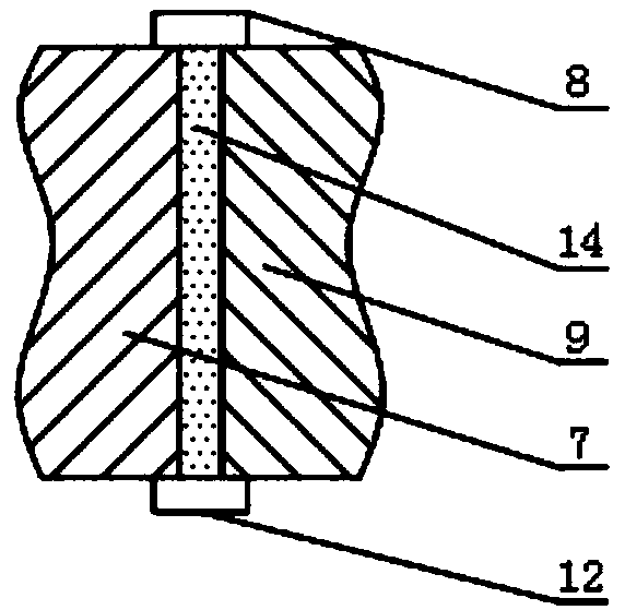
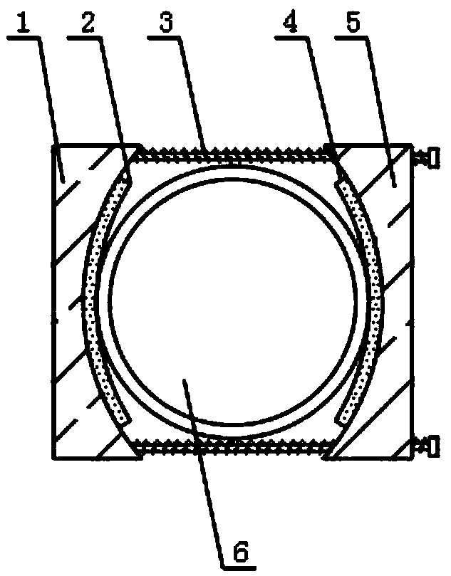
[0022] see Figure 1~4 , in an embodiment of the present invention, a shale gas transmission pipeline includes a first pipeline 6 and a sealing ring 14, one end of the first pipeline 6 is fixedly sleeved with a first fastening ring 7, and the outside of the first pipeline 6 is clamped A protective device 17 is combined, and the protective device 17 includes a first fixed seat 1, a first protective pad 2, a first fastening bolt 3, a second protective pad 4 and a second fixed seat 5, and one end sleeve of the first fastening bolt 3 The first fixed seat 1 is connected, and the other end of the first fastening bolt 3 is sleeved with the second fixed seat 5, the first fixed seat 1 and the second fixed seat 5 are fixedly connected by the first fastening bolt 3, and the second fixed seat 5 A fixed seat 1 and first protective pads 2 are fixed by an adhesive, the front surface of the first fixed seat 1 is fixed with the first protective pad 2, and the rear surface of the second fixed s...


PUM


Abstract

The invention discloses a shale gas conveying pipeline. The conveying pipeline comprises a first pipeline and a sealing ring, a first fastening ring is fixedly connected to one end of the first pipeline in a sleeving mode, and a protection device is clamped outside the first pipeline; a first hoop is connected to the outer portion of a second fastening ring and the outer portion of the first fastening ring in a sleeving mode, and a second hoop is connected to the position, close to the lower portion of the first hoop, of the outer portion of the second fastening ring and the outer portion thefirst fastening ring in a sleeving mode. According to the protection device, the outer portion of the first pipeline can be effectively protected, so that the pipe wall can be prevented from being cracked due to the fact that the pressure in the first pipeline is too large; according to a supporting device, the first pipeline can be effectively supported, so that the first pipeline can be prevented from shaking caused by wind power and external influence; and according to the combined use of the first hoop and the clamping hoop, the leakage of the shale gas in the first pipeline and the secondpipeline can be prevented, and on the other hand, convenience can be brought to the maintenance of workers.

Description

technical field [0001] The invention relates to the technical field of shale gas transportation equipment, in particular to a shale gas transportation pipeline. Background technique [0002] Pipeline refers to the pipeline that transports liquid and gas materials. The method of transporting materials by pipeline is called pipeline transportation. It is a transportation method that specifically transports petroleum, coal and chemical products from the production place to the market. It is the trunk line transportation in the unified transportation network. After shale gas is mined, it needs to be transported through pipelines for subsequent use. [0003] However, most of the conveying pipelines currently on the market are spliced ​​through flanges. Although this can play a sealing role, the installation and disassembly are relatively cumbersome. There will still be sloshing phenomenon, and when the air pressure in the pipeline is high, the pipe wall is prone to cracks, which...

Claims


Application Information

Patent Timeline
Patent Type & Authority Applications(China)
IPC IPC(8): F16L57/02F16L3/02F16L21/06
CPCF16L3/02F16L21/065F16L57/005F16L57/02
Inventor 左宇军孙文吉斌邬忠虎王剑刘镐席仕军税越刘荣波林健云
Owner GUIZHOU UNIV
Learn More