Monitoring lifting bracket with convenient adjustment function

A technology of lifting brackets and functions, which is applied in the direction of machines/supports, supporting machines, closed-circuit television systems, etc. It can solve problems such as difficult to meet the needs of use, and the height cannot be adjusted better, so as to achieve better application effects and wide range of guarantees. Sexuality and the effect of expanding the scope of monitoring

Active Publication Date: 2018-12-21
上海海达通信有限公司
View PDF6 Cites 6 Cited by
  • Summary
  • Abstract
  • Description
  • Claims
  • Application Information

AI Technical Summary

Problems solved by technology

The bracket of the Chinese patent (publication number is CN108413227A) monitoring device has monitoring camera adjustment function and cleaning function in this patent. usage requirements

Method used


Image

  • Monitoring lifting bracket with convenient adjustment function
  • Monitoring lifting bracket with convenient adjustment function
  • Monitoring lifting bracket with convenient adjustment function

Examples


Embodiment 1

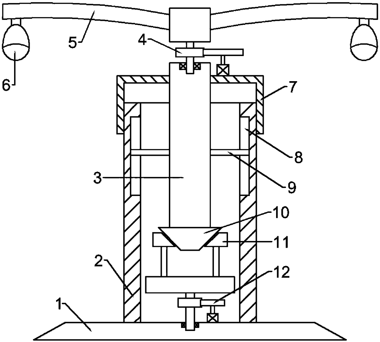
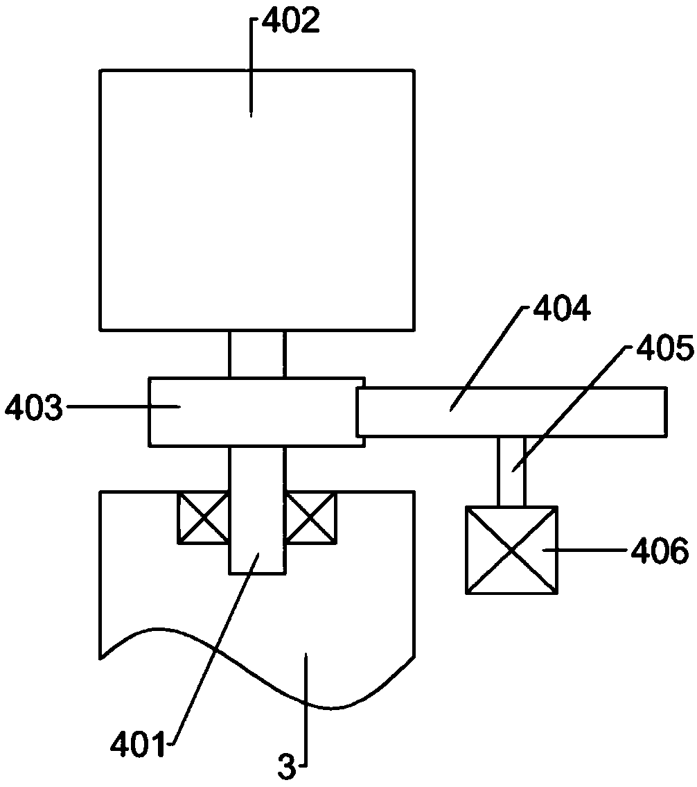
[0024] see figure 1 and figure 2 , in an embodiment of the present invention, a monitoring lifting bracket with a convenient adjustment function includes a base 1, a support sleeve 2 is fixedly connected to the middle of the upper side of the base 1, and a support column 3 is provided at the middle of the support sleeve 2 to support The top of the column 3 is connected with two support arms 5 through the angle adjustment device 4, and the other end of the support arm 5 is provided with a monitoring camera 6 on the lower side. The top of the supporting column 3 is rotationally connected, and the top of the first rotating rod 401 is fixedly connected to the mounting column 402; the middle part of the first rotating rod 401 is fixedly connected to the first driven gear 403, and the right side of the first driven gear 403 is meshed with a first Drive gear 404, the first drive gear 404 lower side is fixedly connected with the first rotating shaft 405, the bottom end of the first ...

Embodiment 2

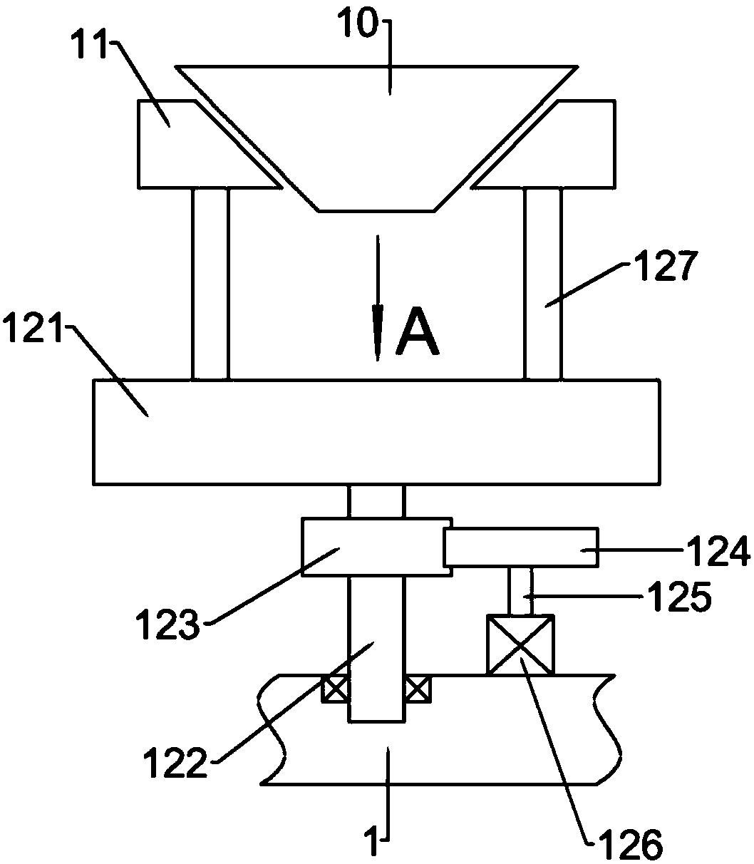
[0026] see figure 1 , image 3 and Figure 4 , the bottom end of the supporting column 3 is fixedly connected with a first mating block 10, the cross section of the first mating block 10 is in the shape of an isosceles trapezoid, and the small end of the first mating block 10 is set downward; the two sides of the first mating block 10 Two second matching blocks 11 are arranged symmetrically on the side, and the cross-section of the second matching blocks 11 is in the shape of a right-angled trapezoid. 121 is provided with two tightening grooves 128 with openings facing upwards. The tightening grooves 128 are arc-shaped, and the center of circle of the tightening grooves 128 does not coincide with the center of circle of the turntable 121. Rod 127, the top of the moving rod 127 is fixedly connected with the second matching block 11; the middle part of the lower side of the turntable 121 is fixedly connected with the second rotating rod 122, the bottom end of the second rotati...


PUM


Abstract

The invention relates to the technical field of monitoring brackets, and in particular to a monitoring lifting bracket with a convenient adjustment function. The bracket comprises a base; a supportingsleeve is fixedly connected at an intermediate portion of the upper side of the base; a supporting column is arranged in the middle of the supporting sleeve; the top of the supporting column is provided with two support arms connected by an angle adjusting device; a monitoring camera is disposed on the lower side of the other end of each support arm; a first mating block is fixedly connected to the bottom end of the supporting column; and the first mating block has an isosceles section, and is set with a small end facing downwards. The monitoring lifting bracket has the following beneficial effects: the angle adjusting device is used to realize the adjustment of the angle of the monitoring cameras, the monitoring of dead angles is facilitated, the monitoring range is expanded, and the application effect is better; the height of the monitoring cameras can be adjusted by a mobile device to facilitate monitoring of different areas; and the monitoring lifting bracket ensures the extensivemonitoring effect and has certain promotion and application value.

Description

technical field [0001] The invention relates to the technical field of monitoring brackets, in particular to a monitoring lifting bracket with a convenient adjustment function. Background technique [0002] The monitoring system is one of the most widely used systems in the security system. The most suitable construction site monitoring system on the market is the handheld video communication device. Video monitoring is now the mainstream; Network video surveillance has undergone earth-shaking changes. Now that IP technology is gradually unifying the world, it is necessary for us to re-understand the development history of video surveillance systems. [0003] In many cases, the monitoring camera is installed on the monitoring bracket, and the angle and height are adjusted with the monitoring bracket as the carrier. The support of the Chinese patent (publication number is CN108413227A) monitoring device has monitoring camera adjustment function and cleaning function in this...

Claims


Application Information

Patent Timeline
Patent Type & Authority Applications(China)
IPC IPC(8): F16M11/04F16M11/08F16M11/18F16M11/28H04N7/18
CPCF16M11/04F16M11/08F16M11/18F16M11/28H04N7/18
Inventor 胡晓东邱明佳陈俊吴骁晨张晨伟
Owner 上海海达通信有限公司
Why Eureka
Try Eureka