

Multiphase flow vertical-type water hole with bi-directional flowing function
A two-way flow, water tunnel technology, used in fluid dynamics tests, testing of machine/structural components, measuring devices, etc., can solve the problems of high investment cost, increased investment cost, large space occupation, etc., to achieve multi-phase flow , to ensure the accuracy of the experiment and improve the effect of the quality of the flow field
- Summary
- Abstract
- Description
- Claims
- Application Information
AI Technical Summary
Problems solved by technology
Method used
Image

Examples
Embodiment 1
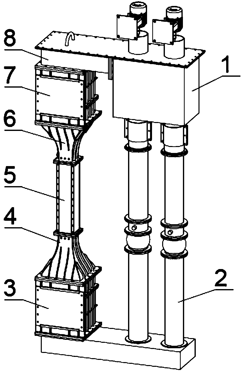
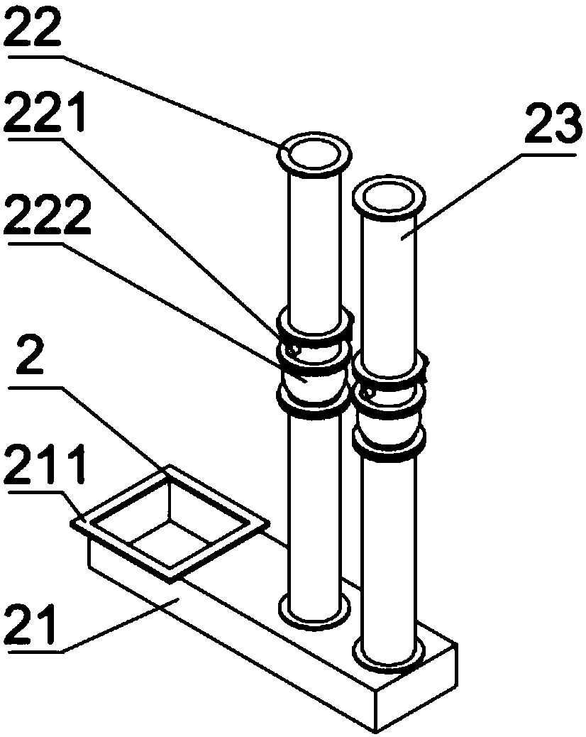
[0032] see figure 1 , figure 2 with image 3 , a multiphase flow vertical water tunnel capable of bidirectional flow, comprising a power section 1, a return section 2, a lower rectifying section 3, a lower diameter reducing section 4, a working section 5, an upper diameter reducing section 6, an upper rectifying section 7 and Upper water tank 8.
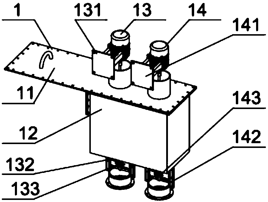
[0033] The upper water tank 8 is horizontally arranged at the upper end of the water tunnel, and the lower end of the upper water tank 8 is connected to the upper rectifying section 7, the upper diameter reducing section 6, the working section 5, the lower diameter reducing section 4 and the lower rectifying section 3 in sequence. The upper end of described upper water tank 8 is provided with upper cover plate 11, and described upper cover plate 11 is a rectangular plate, and one side of the lower side of described upper cover plate 11 is connected on the upper side of upper water tank 8, and described upper cover plate The other...
PUM
 Abstract
Description
Claims
Application Information