A comprehensive design method of notch pattern waveform based on mimo radar

A technology of comprehensive design and pattern, applied in the field of radar, can solve problems such as poor fitting, affecting target detection performance, and inability to effectively suppress interference

Active Publication Date: 2022-07-01
XIDIAN UNIV
View PDF0 Cites 0 Cited by
  • Summary
  • Abstract
  • Description
  • Claims
  • Application Information

AI Technical Summary

Problems solved by technology

[0008] This cost function means: make the covariance matrix of the transmit waveform matrix X as close as possible to the optimal transmit waveform covariance matrix R under the constraints of constant modulus. When the pattern has only the main lobe, the emission obtained by this cost function The waveform matrix can fit the optimal transmit waveform covariance matrix well; when the pattern has both main lobe and notch, this cost function can only fit the optimal transmit waveform covariance matrix well at the main lobe. The variance matrix R cannot fit well at the notch, but in the emission pattern, the notch has the effect of suppressing interference, the deeper the notch, the stronger the ability to suppress interference, the above cost function cannot be in the interference The direction produces a notch, so that the interference cannot be effectively suppressed, and the detection performance of the target is affected

Method used


Image

  • A comprehensive design method of notch pattern waveform based on mimo radar
  • A comprehensive design method of notch pattern waveform based on mimo radar
  • A comprehensive design method of notch pattern waveform based on mimo radar

Examples


Embodiment Construction

[0034] The present invention will be further described below with reference to the accompanying drawings.

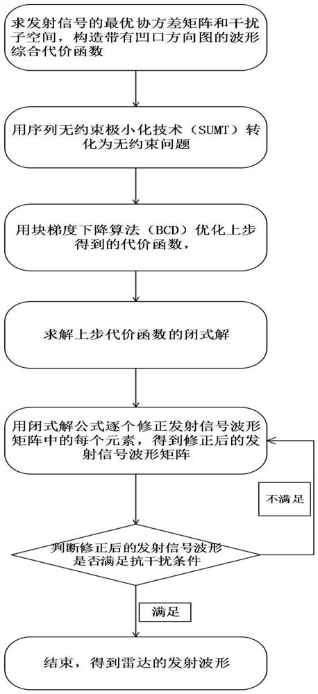
[0035] Refer to the attached figure 1 , the implementation steps of the present invention are as follows:

[0036] Step 1: Calculate the optimal waveform covariance matrix R and interference subspace U of the transmitted signal, and construct a waveform comprehensive cost function with a notch pattern.

[0037] (1a) Construct the interference airspace steering vector, that is, substitute the known azimuth angle of the opposing interference source into the existing steering vector formula to obtain the interference airspace steering vector a(θ s );

[0038]

[0039] Among them, a(θ s ) represents the azimuth angle θ of the opponent's s-th interference source s The spatial steering vector of interference at Represents the distance between radar antenna elements, n represents the serial number of the radar antenna element, the value range of n is [0, N-1], N represe...


PUM


Abstract

The invention discloses a waveform synthesis method with a notch pattern, which solves the problem that the pattern of the existing transmitted signal cannot form a notch in the interference direction. The implementation scheme is: 1. Find the optimal covariance matrix and interference subspace of the transmitted signal, and construct a cost function with a notch pattern; 2. Use the sequence unconstrained minimization method to convert the cost function into an unconstrained function 3. The unconstrained function is optimized by the block gradient descent method to obtain the final cost function; 4. The closed-form solution is obtained by solving the final cost function; 6. Determine whether the corrected transmit waveform satisfies the anti-jamming condition: if so, take the corrected transmit waveform as the radar transmit waveform, if not, take the optimized transmit signal as the initial transmit signal, and return to 5 to continue the iteration. The invention can synthesize the constant-modulus emission waveform with the notch pattern, and can be used for the design of the emission waveform.

Description

technical field [0001] The invention belongs to the technical field of radar, and further relates to a waveform comprehensive design method for a notch pattern, which can be used to design a transmit waveform matrix constrained by constant modulus conditions under the condition that the pattern notch requirements are met, and at the same time make it approach an optimal one. Transmit waveform covariance matrix. Background technique [0002] MIMO radar has multiple transmit and receive antennas, which has become a new research hotspot in the field of radar technology. According to the sparse degree of antennas, MIMO radars can be divided into distributed and centralized types: distributed MIMO radars with larger antenna spacing are called distributed MIMO radars, which have spatial diversity gain performance and can improve the detection ability of scintillating targets; For a centralized MIMO radar with a small antenna spacing, each antenna or each array element can freely ...

Claims


Application Information

Patent Timeline
Patent Type & Authority Patents(China)
IPC IPC(8): G01S7/36G01S13/89
CPCG01S7/36G01S13/89
Inventor 纠博韩露郑浩刘宏伟周生华
Owner XIDIAN UNIV
Why Eureka
Try Eureka