Directional diagram waveform synthesis design method based on notch of MIMO radar

A technology of comprehensive design and pattern, applied in the field of radar, can solve problems such as affecting the performance of target detection, unable to fit well, unable to effectively suppress interference, etc.

Active Publication Date: 2018-12-21
XIDIAN UNIV
View PDF6 Cites 6 Cited by
  • Summary
  • Abstract
  • Description
  • Claims
  • Application Information

AI Technical Summary

Problems solved by technology

[0008] This cost function means: make the covariance matrix of the transmit waveform matrix X as close as possible to the optimal transmit waveform covariance matrix R under the constraints of constant modulus. When the pattern has only the main lobe, the emission obtained by this cost function The waveform matrix can fit the optimal transmit waveform covariance matrix well; when the pattern has both main lobe and notch, this cost function can only fit the optimal transmit waveform covariance matrix well at the main lobe. The variance matrix R cannot fit well at the notch, but in the emission pattern, the notch has the effect of suppressing interference, the deeper the notch, the stronger the ability to suppress interference, the above cost function cannot be in the interference The direction produces a notch, so that the interference cannot be effectively suppressed, and the detection performance of the target is affected

Method used


Image

  • Directional diagram waveform synthesis design method based on notch of MIMO radar
  • Directional diagram waveform synthesis design method based on notch of MIMO radar
  • Directional diagram waveform synthesis design method based on notch of MIMO radar

Examples


Embodiment Construction

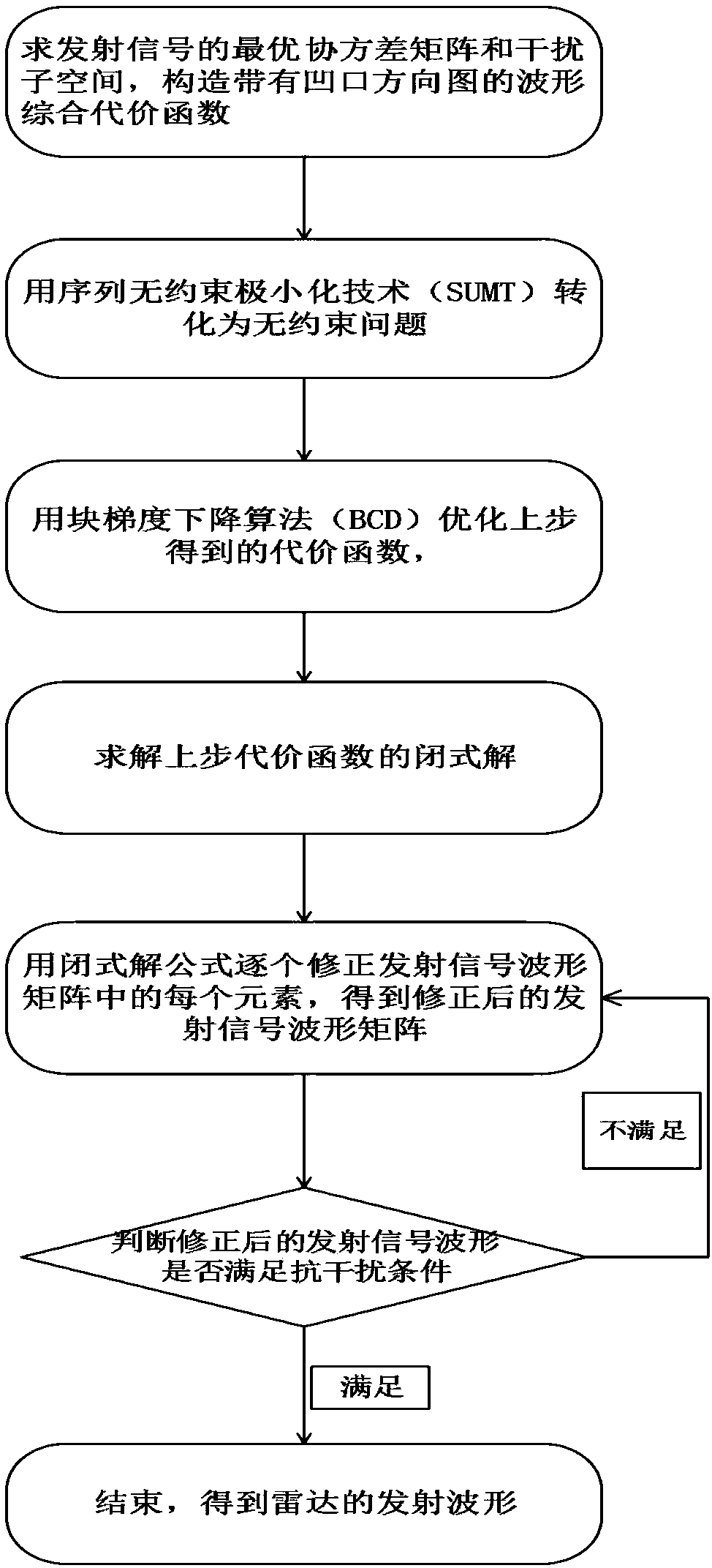
[0034] The present invention will be further described below in conjunction with the drawings.

[0035] Reference attached figure 1 , The implementation steps of the present invention are as follows:

[0036] Step 1: Calculate the optimal waveform covariance matrix R and the interference subspace U of the transmitted signal, and construct the comprehensive cost function of the waveform with the notch pattern.

[0037] (1a) Construct the interference airspace steering vector, that is, substitute the known azimuth angle of the other side interference source into the existing steering vector formula to obtain the interference airspace steering vector a(θ s );

[0038]

[0039] Where a(θ s ) Represents the azimuth angle θ of the other side's sth interference source s The interference airspace steering vector at, the value range of s is [1,K], K represents the total number of interference sources, exp represents the exponential operation based on the natural constant, j represents the imag...


PUM


Abstract

The invention discloses a waveform synthesis method for a directional diagram provided with a notch and solves the problem that a directional diagram of an existing transmitting signal can not form anotch in an interference direction. According to an implementation scheme, the method comprises the following steps: firstly, finding an optimal covariance matrix and an interference subspace of a transmitting signal, and constructing a cost function of the directional diagram provided with the notch; secondly, converting the cost function into an unconstrained function by adopting a sequential unconstrained minimization method; thirdly, optimizing an unconstrained function by adopting a block gradient descent method, thus a final cost function is obtained; fourthly, solving the final cost function, thus a closed-form solution is obtained; fifthly, correcting an initial transmitting signal by using the closed-form solution, thus a corrected transmitting signal matrix is obtained; and sixthly, judging whether a corrected transmitted waveform meets anti-interference conditions, if the corrected transmitted waveform meets the anti-interference conditions, taking the corrected transmittedwaveform as a transmitted waveform of a radar, and if the corrected transmitted waveform does not meet the anti-interference conditions, taking an optimized transmitting signal as the initial transmitting signal, and returning to the step 5 and continuously iterating. The method disclosed by the invention can synthesize a constant modulus transmitted waveform of the directional diagram provided with the notch and can be used for design of the transmitted waveform.

Description

Technical field [0001] The present invention belongs to the field of radar technology, and further relates to a method for comprehensively designing a wave pattern of a notch pattern, which can be used to design a transmission waveform matrix constrained by constant modulus conditions while meeting the requirements of the pattern notch, and at the same time make it approach the optimal Transmit waveform covariance matrix. Background technique [0002] MIMO radar has multiple transmitting antennas and receiving antennas, and has become a new research hotspot in the field of radar technology. According to the sparseness of the antennas, MIMO radars can be divided into two types: distributed and centralized: the antennas with larger antenna spacing are called distributed MIMO radars, which have spatial diversity gain performance and can improve the detection ability of scintillating targets; For centralized MIMO radar with small antenna spacing, each antenna or each element of its ...

Claims


Application Information

Patent Timeline
Patent Type & Authority Applications(China)
IPC IPC(8): G01S7/36G01S13/89
CPCG01S7/36G01S13/89
Inventor 纠博韩露郑浩刘宏伟周生华
Owner XIDIAN UNIV
Why Eureka
Try Eureka