Method and system for measuring pitting area ratio of tooth surface
An area ratio and tooth surface technology, which is applied in the field of pitting corrosion area ratio measurement methods and systems on tooth surfaces, can solve the problems of large manual workload, high error rate, low efficiency, etc., and achieves improved measurement efficiency, improved objectivity, and reduced The effect of manual measurement of burden
- Summary
- Abstract
- Description
- Claims
- Application Information
AI Technical Summary
Problems solved by technology
Method used
Image

Examples
Embodiment 1
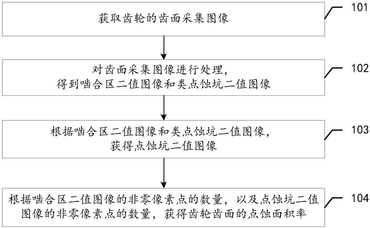
[0076] see figure 1 , which is a flow chart of the method for measuring the tooth surface pitting area ratio provided by the embodiment of the present application.
[0077] Such as figure 1 As shown, the tooth surface pitting area ratio measurement method provided in this embodiment includes:
[0078] S101: Acquiring tooth surface acquisition images of gears.
[0079] First of all, it is necessary to understand the interrelationship between gear tooth surface, meshing area, pitting pit and pitting area rate.
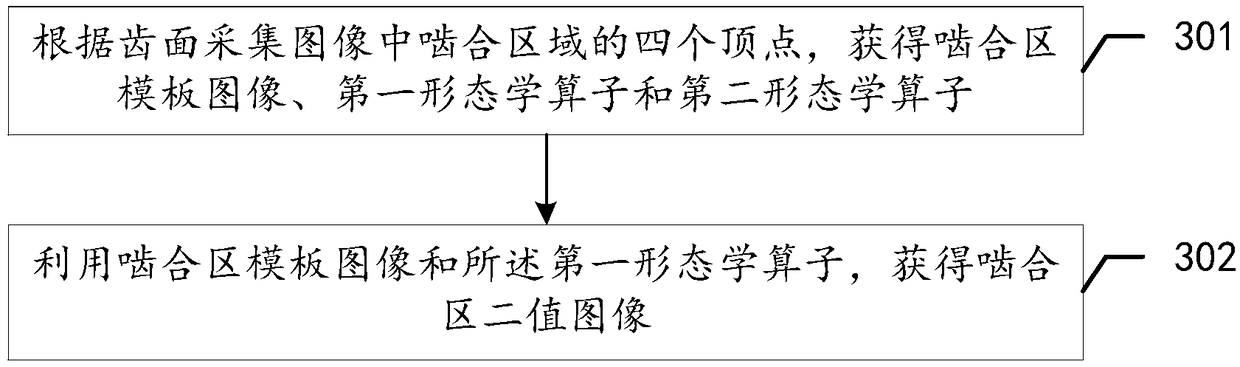
[0080] The gears contain a plurality of teeth, and each tooth contains two tooth faces, a front face and a reverse face, for intermeshing with the teeth of other gears. There is a meshing area on each tooth surface of each tooth, and pitting pits are formed on the meshing area due to long-term wear. Pitting pits are mainly distributed in the meshing area of the tooth surface. The pitting area ratio refers to the area occupancy of pitting pits in the meshing area o...
Embodiment 2
[0157] see Figure 5 , which is a flow chart of the method for measuring the tooth surface pitting area ratio provided in this embodiment.
[0158] Such as Figure 5 As shown, the method for measuring the tooth surface pitting area ratio provided in the embodiment of the present application includes:
[0159] S501: at a preset time interval t 1 Take a picture of the front side of the tooth surface of the gear, and obtain an image of the front side of the tooth surface of the gear.
[0160] In this example, t 1 = 0.5 seconds. Write down the acquisition time t of the frontal image acquisition of a certain tooth surface.
[0161] S502: Process the collected image of the front surface of the tooth surface by the region of interest segmentation method, and determine the collected image of the front surface of the tooth surface that meets the requirements.
[0162] In this embodiment, with the threshold T gThreshold segmentation is performed on the collected image of the fron...
PUM
| Property | Measurement | Unit |
|---|---|---|
| Diameter | aaaaa | aaaaa |
Abstract
Description
Claims
Application Information
 - Generate Ideas
- Intellectual Property
- Life Sciences
- Materials
- Tech Scout
- Unparalleled Data Quality
- Higher Quality Content
- 60% Fewer Hallucinations
Browse by: Latest US Patents, China's latest patents, Technical Efficacy Thesaurus, Application Domain, Technology Topic, Popular Technical Reports.
© 2025 PatSnap. All rights reserved.Legal|Privacy policy|Modern Slavery Act Transparency Statement|Sitemap|About US| Contact US: help@patsnap.com