Illumination module for angle-selective illumination

A lighting module, partially ground technology, applied in the field of laser scanning microscope and microscope, can solve the problem of limited structural space and so on

Active Publication Date: 2018-12-21
CARL ZEISS MICROSCOPY GMBH
View PDF9 Cites 0 Cited by
  • Summary
  • Abstract
  • Description
  • Claims
  • Application Information

AI Technical Summary

Problems solved by technology

[0003] To some extent it may be difficult to combine corresponding illumination modules for angularly selectable illumination with conventional optical devices such as laser...

Method used


Image

  • Illumination module for angle-selective illumination
  • Illumination module for angle-selective illumination
  • Illumination module for angle-selective illumination

Examples


Embodiment Construction

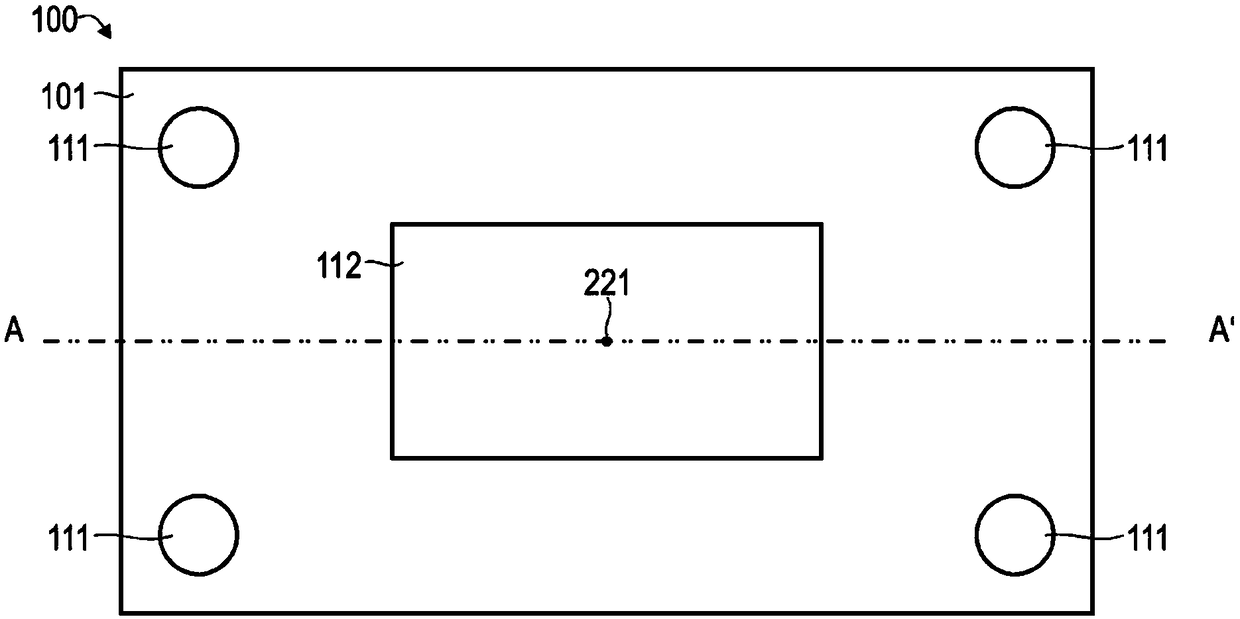
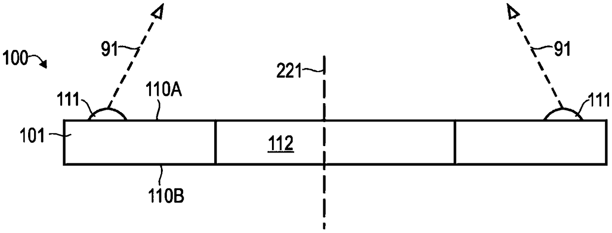
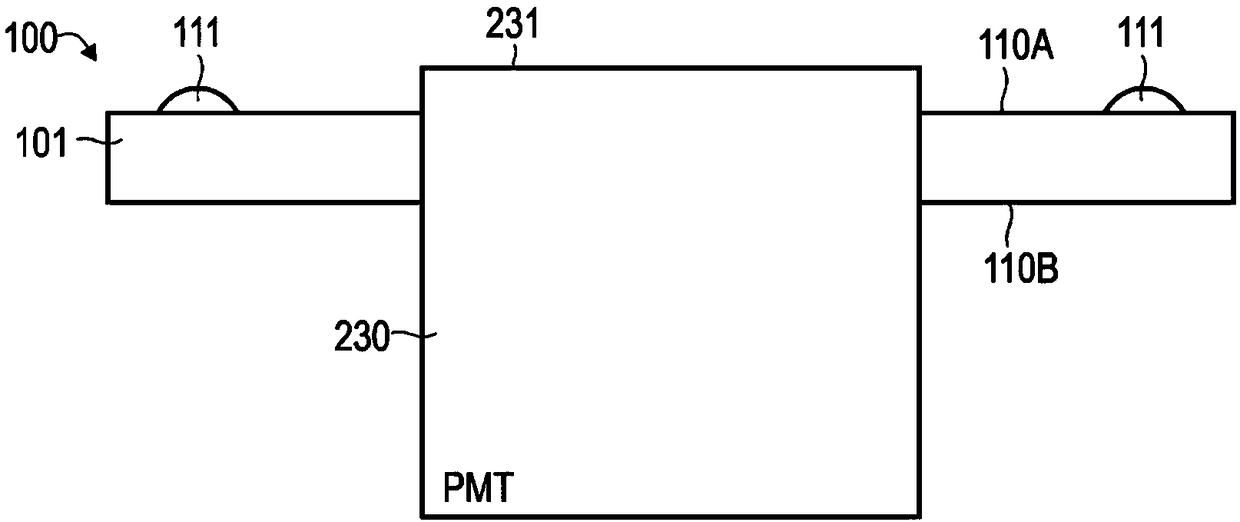
[0087] The invention is explained in more detail below on the basis of preferred embodiments with reference to the drawings. In the figures the same reference numbers designate the same or similar elements. The figures are schematic representations of different embodiments of the invention. Elements shown in the figures are not necessarily shown to scale. Rather, the different elements shown in the drawings are intended to make their functions and main purposes understandable to those skilled in the art.

[0088] The technology related to the illumination module, which can be used to illuminate the sample at a selectable angle, is described below. The illumination module comprises a plurality of light sources which are arranged at a distance from one another and thus enable illumination of the sample from several illumination directions. The measurement images corresponding to the individual lighting directions can then be combined with one another. A resulting image with ...


PUM


Abstract

The invention relates to an optical device comprising an illumination module (100) with a carrier (110) which has, for example, at least one light-permeable region (112). The illumination module (100)comprises a plurality of light sources (111) that are arranged on the carrier (110).

Description

technical field [0001] Various embodiments of the invention relate to laser scanning microscopes and microscopes. In various embodiments, a lighting module for a corresponding optical device comprises a carrier with a plurality of light sources and optionally at least one light-transmitting region. Background technique [0002] Illumination of a sample from different illumination directions (angle-selectable illumination or structured illumination) is known from DE 10 2014 112 242 A1. By combining the images acquired for different illumination directions a result image can be determined, for example with phase contrast. Phase-contrast imaging can thus be achieved by digital post-processing with the aid of angle-selectable illumination. [0003] To some extent it can be difficult to combine appropriate illumination modules for angularly selectable illumination with conventional optical devices such as laser scanning microscopes (LSM) or optical microscopes with objective le...

Claims


Application Information

Patent Timeline
IPC IPC(8): G02B21/08G02B21/14G02B21/36
CPCG02B21/084G02B21/086G02B21/088G02B21/14G02B27/58G02B21/367G02B21/0032G01N21/6402G01N21/6458G01N2201/06113G02B21/008G02B21/16G06T5/50G06T7/55G06T7/70G02B21/26G06T2207/10056G06T2207/10152
Inventor 拉尔斯·施托佩迈克尔·戈格勒托马斯·奥尔特
Owner CARL ZEISS MICROSCOPY GMBH
Why Eureka
Try Eureka