Lighting module with heat exchange device with closed-cell metal foam

A heat exchange device and lighting module technology, applied in the field of vehicles, can solve the problems of high cost, weight, and high energy efficiency, and achieve the effects of low weight, reduced manufacturing costs, and reduced costs

Pending Publication Date: 2021-03-12
FORD GLOBAL TECH LLC
View PDF4 Cites 0 Cited by
  • Summary
  • Abstract
  • Description
  • Claims
  • Application Information

AI Technical Summary

Problems solved by technology

Lighting modules typically have higher cost and weight

Method used


Image

  • Lighting module with heat exchange device with closed-cell metal foam
  • Lighting module with heat exchange device with closed-cell metal foam
  • Lighting module with heat exchange device with closed-cell metal foam

Examples


Embodiment Construction

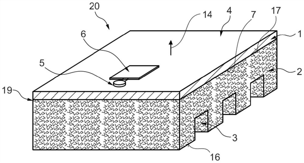
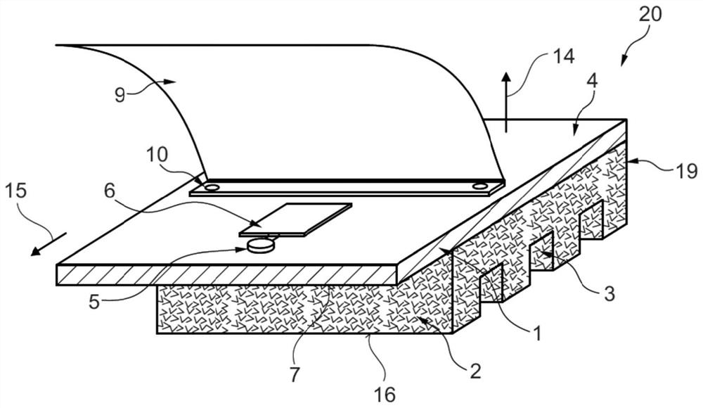
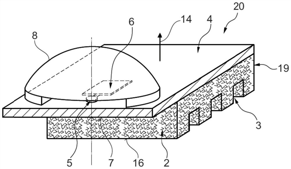
[0032] figure 1A perspective view and a partial sectional view of the lighting module 20 according to the invention are schematically shown. The lighting module 20 comprises a heat exchange device 19 and at least one semiconductor light source 5 (eg LED). The heat exchange device 19 comprises a first metal plate 1 which is directly connected, in particular metallurgically, to the closed-cell metal foam 2 . In particular direct connections for metallurgical connections are best produced by powder metallurgy processes. In this way, a one-piece heat exchange device is made from metal plate 1 and metal foam 2 . The metal plate 1 has an upper side 4 with a surface normal 14 . The metal foam 2 is arranged on the underside 7 of the metal plate 1 . In the variant shown, the semiconductor light sources 5 and the printed circuit board 6 are arranged on the top 4 of the metal plate 1 . The semiconductor light sources 5 will be cooled by heat exchange means 19 . In principle, furthe...


PUM


Abstract

The invention describes a lighting module (20) having a heat exchange device (19) for cooling at least one semiconductor light source (5). The heat exchange device (19) comprises at least one metal plate (1) having an upper side (4) and a lower side (7), wherein a closed-cell metal foam (2) metallurgically connected with the metal plate (1) is provided on the lower side (7), and at least one semiconductor light source (5) is arranged on the upper side (4), so that the light source is in direct thermal contact with the metal plate (1).

Description

technical field [0001] The invention relates to a lighting module having a heat exchange device for cooling at least one semiconductor light source. The invention also relates to a headlight for a vehicle and to a vehicle. Background technique [0002] With regard to headlights of motor vehicles, there is currently a tendency to replace halogen headlights with lighting modules in which reflected LED light is used for illumination in the headlights. Lighting modules generally have higher cost and weight than halogen headlamps, but are more energy efficient. Therefore, optimization of cost and weight is extremely important for the continued use of LEDs. A decisive cost and weight component in relation to lighting modules is caused by the necessary lighting modules, which generally contain at least one heat exchange device, a printed circuit board and a plurality of LEDs. Most of the weight of the lighting module falls on the heat exchange device. The type and material used...

Claims


Application Information

Patent Timeline
IPC IPC(8): F21S41/141F21S41/25F21S41/30F21S45/47F21V29/503F21V29/89F21W107/10F21Y115/10
CPCF21S41/141F21S41/25F21S41/30F21S45/47F21V29/503F21V29/89F21W2107/10F21Y2115/10F21S41/143F21S41/148F21S41/192F21S41/255F21S41/321F21S41/39
Inventor 亚历山大·诺伊施塔特弗兰克·欧斯特
Owner FORD GLOBAL TECH LLC
Why Eureka
Try Eureka