
Common phase error compensation

A phase error, associated technology, applied in the field of error compensation, to achieve the effect of improving resource utilization

Active Publication Date: 2018-12-21
TELEFON AB LM ERICSSON (PUBL)
View PDF8 Cites 0 Cited by
  • Summary
  • Abstract
  • Description
  • Claims
  • Application Information

AI Technical Summary

Problems solved by technology

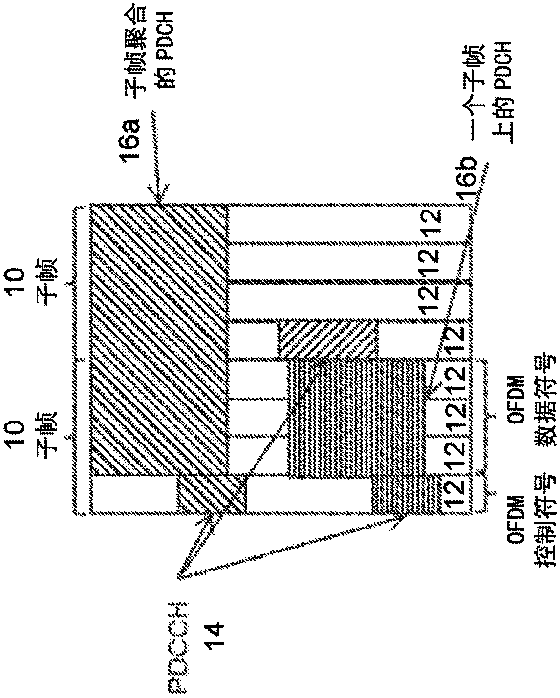
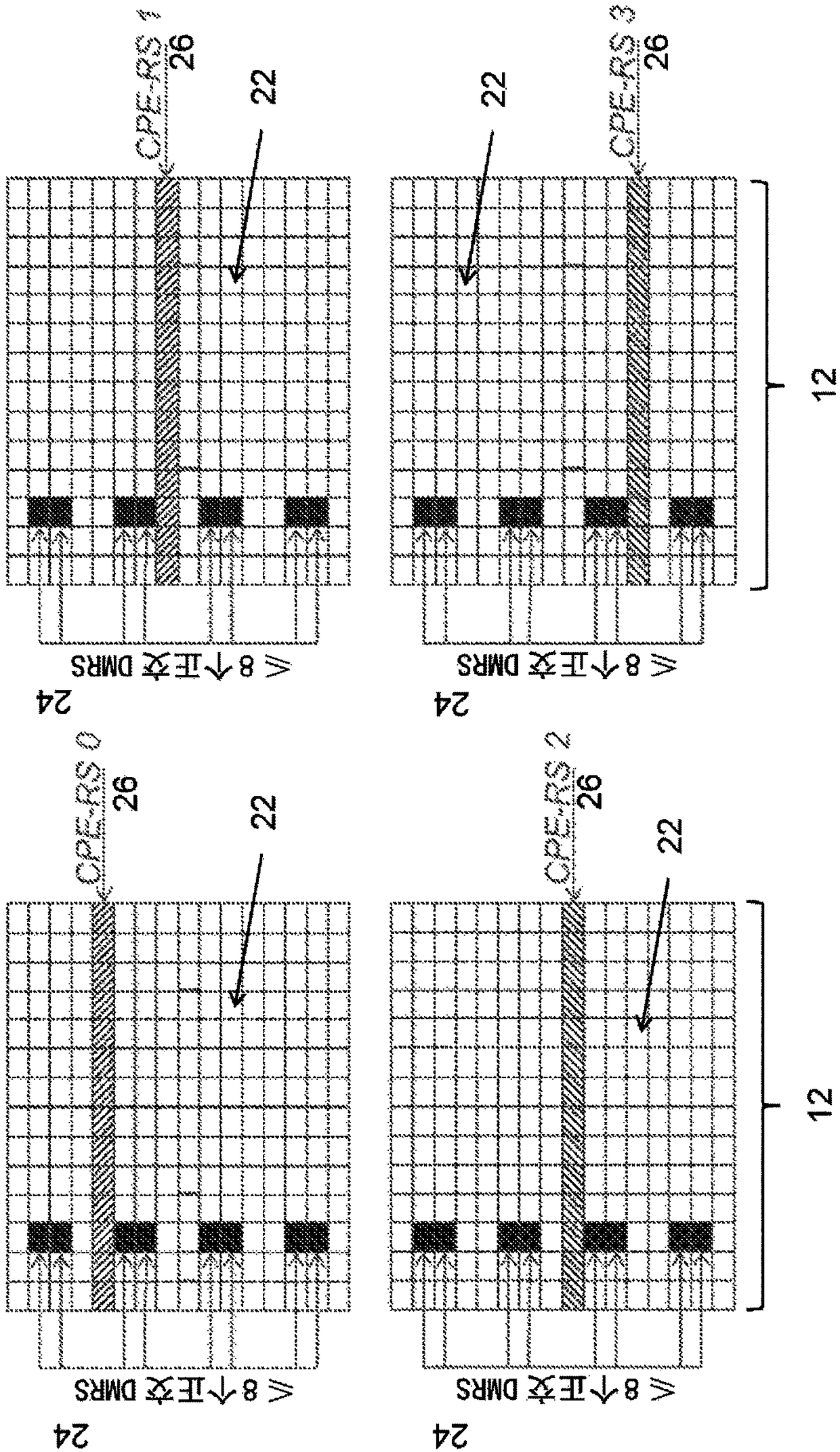
However, this creates a problem when the subcarriers used for common phase error tracking are blocked (crossed) by OFDM symbols used for DM-RS (which also contain common phase errors and require a phase error reference)

Method used


Image

  • Common phase error compensation
  • Common phase error compensation
  • Common phase error compensation

Examples


Embodiment Construction

[0046] A conventional synchronous radio system includes an always-on downlink signal (eg, PSS / SSS / CRS in LTE) that enables the UE to track the time-frequency synchronization of the base station without communicating with the network. This design simplifies time-frequency synchronization, but at the cost of poor energy performance and constant interference from always-on signals.

[0047] A thin system design that eliminates signals that are always present is another option. However, the consequence of eliminating an ever-present signal such as CRS is that tracking and fine-tuning of time-frequency synchronization becomes more complicated. Relying on DM-RS for time-frequency synchronization will incur significant overhead as it uses most of the spectrum for synchronization at the expense of reduced data rates. For example, using DM-RS to track common phase errors is inefficient because the required time density is high for accurate common phase error tracking. DM-RS is design...


PUM


Abstract

According to some embodiments, a method in a wireless receiver of compensating common phase error in a received wireless signal comprises receiving a first symbol of a wireless signal. The first symbol comprises a code division multiplexed demodulation reference signal (DM-RS) multiplexed with a length M orthogonal cover code, and a first code division multiplexed common phase error reference signal (CPE-RS) multiplexed with a length N orthogonal cover code, wherein N is less than or equal to M. The method further comprises determining M code points in the first symbol associated with a DM-RS;estimating a channel corresponding to the received wireless signal using the M code points associated with the DM-RS; estimating a first CPE-RS corresponding to the estimated channel using the firstN code points of the M code points associated with the DM-RS; and compensating the estimated channel for phase error using the estimated first CPE-RS.

Description

technical field [0001] Particular embodiments relate generally to error compensation in wireless communication networks, and more particularly to common phase error reference signals. Background technique [0002] Communications between wireless transmitters and receivers often require synchronization in time and / or frequency in order to receive messages reliably. In cellular systems such as 3rd Generation Partnership Project (3GPP) Long Term Evolution (LTE) or LTE New Radio (LTENR, LTE-NX, or LTE 5G), base stations periodically broadcast narrowband synchronization signals (PSS / SSS ). Based on the synchronization signal, a wireless device accessing the system can perform an initial cell search (ie, a synchronization procedure including finding the carrier frequency, time reference instant, and cell identity). [0003] Then, the LTE device that has performed the initial cell search and recognized the cell identity can complete the initial synchronization in the downlink by ...

Claims


Application Information

Patent Timeline
IPC IPC(8): H04L5/00H04L27/26H04J13/18
CPCH04J13/0048H04J2011/0016H04L5/0051H04L27/2675H04B1/12H04L5/026H04L25/0226
Inventor 马丁·赫斯勒拉尔斯·林德布姆约翰·福鲁斯克
Owner TELEFON AB LM ERICSSON (PUBL)
Learn More