Support for maxillary sinus floor elevation space maintenance and use method of support

A pillar and maxillary sinus technology, applied in the field of pillars for maintaining the lifting space of the maxillary sinus floor, can solve problems such as difficulty in maintaining the lifting space

Pending Publication Date: 2018-12-25
福建医科大学附属口腔医院
View PDF0 Cites 0 Cited by
  • Summary
  • Abstract
  • Description
  • Claims
  • Application Information

AI Technical Summary

Problems solved by technology

[0003] The purpose of the present invention is to reduce the defect that the lifting space of the existing maxillary sinus floor without bone grafti

Method used


Image

  • Support for maxillary sinus floor elevation space maintenance and use method of support
  • Support for maxillary sinus floor elevation space maintenance and use method of support
  • Support for maxillary sinus floor elevation space maintenance and use method of support

Examples


Embodiment 1

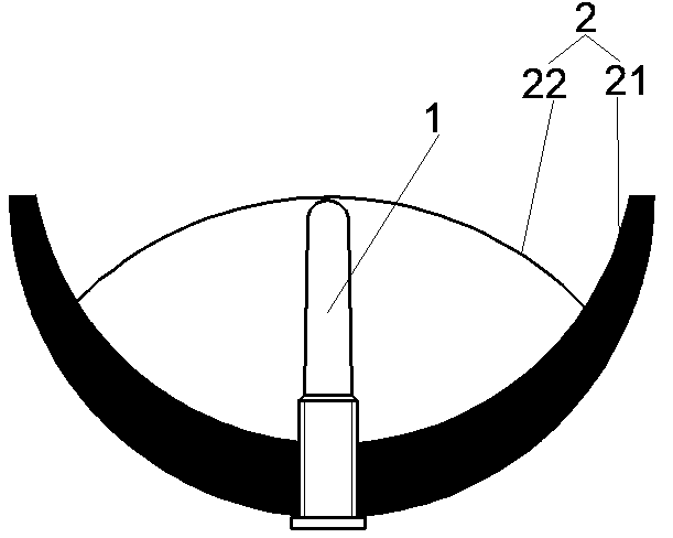
[0031] Such as figure 1 , 2 As shown, the present invention provides a pillar 1 for maintaining the maxillary sinus floor lifting space, the cross-section of the pillar is circular, and the cross-sectional diameter at any position is not greater than the cross-sectional diameter at the lower end position, so that it is easy to enter the upper jaw sinus. From top to bottom, the pillars are blunt part 11, smooth section 12, threaded section 13 and protruding section 14. Both smooth section 12 and threaded section 13 can be cylindrical or conical, including but not limited to the following situations: 1) Both the smooth section 12 and the threaded section 13 are cylindrical; 2) The smooth section 12 and the threaded section 13 are both conical; 3) The smooth section 12 is cylindrical, and the threaded section 13 is conical; 4) The smooth section 12 is conical , Thread segment 13 is cylindrical (such as figure 1 , 4 , 5). In either case, the precondition that the cross-sectio...

Embodiment 2

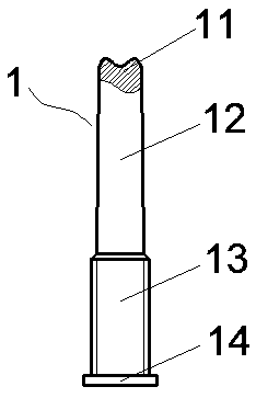
[0043] Such as Figure 4 As shown, the difference between embodiment 2 and embodiment 1 is that the upper surface of the blunt portion of the pillar is a concave arc surface in the middle. Several situations listed in Example 1 are used in the same way.

Embodiment 3

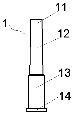
[0045] Such as Figure 5 As shown, the difference between embodiment 3 and embodiment 1 is that the upper surface of the blunt part of the pillar is a plane, and the rest of the structure is the same as that of embodiment 1, and the shapes of the smooth section 12 and the threaded section 13 can also be listed in embodiment 1. In several situations, the method of use is the same.


PUM

PropertyMeasurementUnit
Diameteraaaaaaaaaa
Diameteraaaaaaaaaa
Lengthaaaaaaaaaa

Abstract

A support for maxillary sinus floor elevation is integrally elongated and has a circular section. A blunt portion, a smooth section, a threaded section and a projecting section are sequentially arranged on the support from top to bottom, the sectional radius of an optional position of the support is not larger than that of an optional downward position, the projecting section is a radial expansionportion at the lower end of the threaded section, the blunt portion is integrally smooth, and the lower end face of the projecting section is provided with a groove. When the support is mounted, theblunt portion, the smooth section and the threaded section are sequentially screwed into a maxillary sinus cavity from bottom to top until the projecting section can be clamped at an alveolar ridge crest of a local area of maxillary molar. The section of the support is circular, the diameter of the upper end of the support is not larger than that of the lower end of the support, and the support iseasily inserted into a maxillary sinus. The smooth blunt portion can support a maxillary sinus floor mucous membrane, and the maxillary sinus floor mucous membrane cannot be pierced. The threaded section can maintain the stability of the support by the aid of the height of a local area alveolar bone, and the groove in the lower end face of the projecting section is used for assembling or disassembling the support.

Description

technical field [0001] The invention relates to the technical field of oral and maxillary sinus floor lifting, in particular to a pillar for maintaining a space for maxillary sinus floor lifting and a method of use thereof. Background technique [0002] Due to factors such as continuous gasification of the maxillary sinus cavity and alveolar bone absorption after edentulousness, the height of the alveolar bone in the maxillary posterior teeth area is often insufficient, which limits the implant restoration in this area to a large extent, and the maxillary sinus floor is required. Lifting. At present, in clinical practice, maxillary sinus floor augmentation and simultaneous implantation of bone substitute materials are routine procedures for insufficient bone in the maxillary posterior region. However, the use of bone substitute materials and barrier membranes will not only increase the economic burden and postoperative discomfort of patients, but may also cause immune react...

Claims


Application Information

Patent Timeline
IPC IPC(8): A61C8/00
CPCA61C8/0092
Inventor 刘瑞敏鄢明东吴东黄文秀陈江周勇
Owner 福建医科大学附属口腔医院
Why Eureka
Try Eureka