Argon-rich tail gas oil-removing system for crystal pulling furnace

A technology of crystal pulling furnace and oil system, applied in the field of argon-rich tail gas degr The effect of the failure rate

Pending Publication Date: 2018-12-25
湖北和远气体股份有限公司
View PDF1 Cites 3 Cited by
  • Summary
  • Abstract
  • Description
  • Claims
  • Application Information

AI Technical Summary

Problems solved by technology

[0005] In the invention patent with the application number CN201721189615.9, the simple H-shaped tube plus oil removal adsorption barrel mode cannot purify the oil to the effect required by the process
[0006] Crystal pulling manufacturers generally have hundreds of crystal pulling furnaces. These crystal pulling furnaces are distributed in multiple workshops. To recover these exhaust gases after degreasing, the invention patent with application number CN201721189615.9 is used in each workshop Install the fan, send the tail gas of the workshop into the fan through the pipeline, and then gather the fans of each workshop into the main pipe. The disadvantage of this solution is that there are too many fans, and the fans are dynamic equipment that consumes electricity. Once a fan fails , the gas of other fans will flow back through the faulty fan, so that the gas cannot be recovered

Method used


Image

  • Argon-rich tail gas oil-removing system for crystal pulling furnace
  • Argon-rich tail gas oil-removing system for crystal pulling furnace
  • Argon-rich tail gas oil-removing system for crystal pulling furnace

Examples


Embodiment Construction

[0036] In order to make the objectives, technical solutions, and advantages of the present invention clearer, the following further describes the present invention in detail with reference to the accompanying drawings and embodiments. It should be understood that the specific embodiments described here are only used to explain the present invention, but not to limit the present invention.

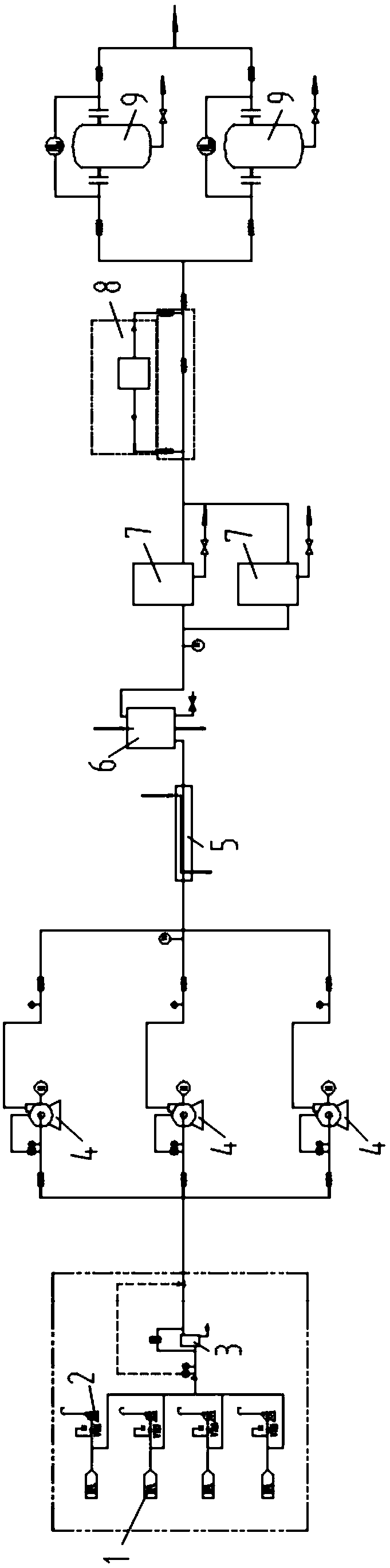
[0037] Such as figure 1 As shown, an argon-rich tail gas degreasing system for a crystal pulling furnace includes at least one vacuum pump 2 connected to the argon-rich tail gas pipeline 1 and a wire mesh filter 3 connected to the vacuum pump 2 arranged in sequence along the direction of the tail gas intake. A fan 4 connected to the wire mesh filter 3, a cooler 6 connected to the fan 4, at least one filter element filter 7 connected to the cooler 6, an electrostatic oil removal device 8 connected to the filter element filter 7, at least A deoiling adsorption cylinder 9 connected to the electro...


PUM


Abstract

The invention relates to an argon-rich tail gas oil-removing system for a crystal pulling furnace. The argon-rich tail gas oil-removing system for the crystal pulling furnace comprises at least one vacuum pump, a silk screen filter, at least one fan, a cooler, at least one cartridge filter, an electrostatic oil-removing device, at least one deoiling adsorption barrel and a gas cabinet, wherein thevacuum pumps, the silk screen filter, the fans, the cooler, the cartridge filters, the electrostatic oil-removing device, the deoiling adsorption barrel and the gas cabinet are successively arrangedin the tail gas inlet direction; the vacuum pumps are connected with an argon-rich tail gas pipe; the silk screen filter is connected with the vacuum pump; the fans are connected with the silk screenfilter; the cooler is connected with the fans; the cartridge filters are connected with the cooler; the electrostatic oil-removing device is connected with the cartridge filters; the deoiling adsorption barrels are connected with the electrostatic oil-removing device; and the gas cabinet is connected with the deoiling adsorption barrels. Multiple combination modes are used to remove oil in argon-rich tail gas step by step, the follow-up low-temperature purifying requirement is met, meanwhile, the number of the fans is reduced, only three fans are used, mobile devices are reduced, and therefore, the failure rate is reduced.

Description

Technical field [0001] The invention relates to the technical field of oil and gas separation, in particular to an argon-rich tail gas degreasing system of a crystal pulling furnace. Background technique [0002] Monocrystalline silicon solar energy companies need to fill a large amount of high-purity argon into a polycrystalline silicon production furnace or a monocrystalline silicon production furnace during the production process as a protective gas to prevent air from entering. The tail gas containing argon is drawn out by the vacuum pump and discharged into the atmosphere, causing waste. The argon content in the argon-rich tail gas discharged during the production of monocrystalline silicon is as high as 98%, which has high extraction value. The argon-rich tail gas discharged at the same time contains CO and CH 4 , Hydrocarbons, oil, dust and other substances that pollute the air and harm the human body. [0003] At the same time, the argon-rich tail gas contains oil and dus...

Claims


Application Information

Patent Timeline
IPC IPC(8): B01D50/00B01D5/00B01D53/00
CPCB01D5/0012B01D5/0072B01D50/00B01D53/002B01D2258/02
Inventor 杜大艳袁有录杨涛焦文艺刘隆益
Owner 湖北和远气体股份有限公司
Why Eureka
Try Eureka