
Plate bending machine and method

A technology for bending machines and plates, applied in the field of plate bending machines, can solve the problems of inaccurate right-angle bending, easy generation of cold brittleness, affecting austenite transformation, etc., to improve bending accuracy and save intermediate swivels process, the effect of improving bending stability

Pending Publication Date: 2018-12-25
大连绿云科技有限公司
View PDF9 Cites 7 Cited by
  • Summary
  • Abstract
  • Description
  • Claims
  • Application Information

AI Technical Summary

Problems solved by technology

[0003] The traditional bending machine is not accurate for right-angle bending when bending the plate, and the corresponding equipment needs to be replaced. The plate is air-cooled in the air after staying in the air for a long time during the replacement, which will affect the transformation of austenite. produce cold and brittle phenomenon

Method used


Image

  • Plate bending machine and method
  • Plate bending machine and method
  • Plate bending machine and method

Examples


Embodiment 1

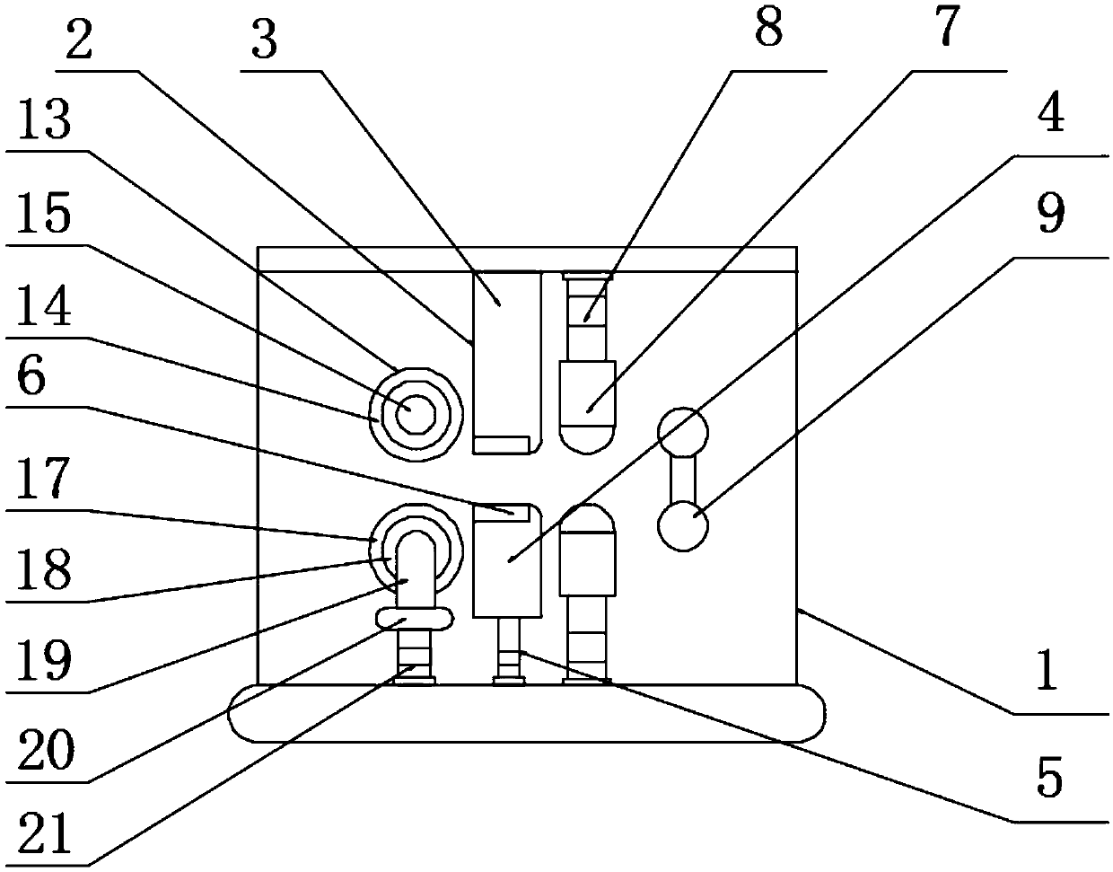
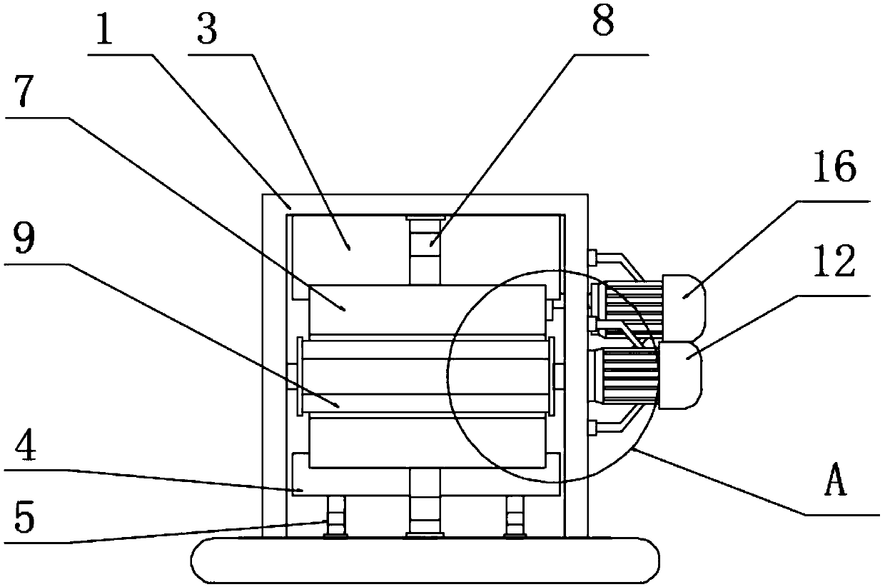
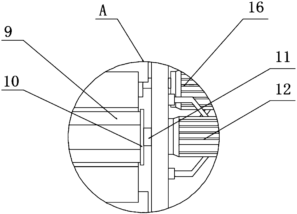
[0025] The present invention provides such Figure 1-3 The plate bending machine shown includes a chassis 1, and a bending device 2 is provided inside the chassis 1. The bending device 2 includes an upper fixing block 3, and the upper fixing block 3 is fixedly connected to the chassis 1. The bottom of the upper fixed block 3 is provided with a lower fixed block 4, the bottom of the lower fixed block 4 is provided with a first hydraulic rod 5, the output shaft of the first hydraulic rod 5 is fixedly connected with the lower fixed block 4, and the upper fixed block A heater 6 is provided on the surface of the block 3 and the lower fixed block 4, and a bending block 7 is provided on one side of the upper fixing block 3 and the lower fixing block 4, and a second hydraulic rod 8 is provided at one end of the bending block 7, The output shaft of the second hydraulic rod 8 is fixedly connected with the bending block 7, and the cross-sectional shape of one end of the bending block 7 i...

Embodiment 2

[0035] A sheet bending method, including the sheet bending machine, also includes the following steps:

[0036] S1: Conveying the forged plate between the upper fixing block 3 and the lower fixing block 4;

[0037]S2: Turn on the heater 6 to heat the plate to ensure that the plate is in a high temperature state;

[0038] S3: Open the second hydraulic rod 8 when it is necessary to perform intermediate bending, push the bending block 7 through the second hydraulic rod 8 to bend the plate upward or downward, and at the same time, the second hydraulic rod 8 pushes the bending block at the same time 7 to fix the plate;

[0039] S4: Turn on the stepping motor 12, and the stepping motor 12 drives the bending roller 9 through the first rotating shaft 11 to bend the plate in a corresponding arc.


PUM


Abstract

The invention discloses a plate bending machine and method. The plate bending machine comprises a case, a bending device is arranged in the case, the bending device comprises an upper fixing block, the upper fixing block is fixedly connected with the case, a lower fixing block is arranged at the bottom of the upper fixing block, a first hydraulic rod is arranged at the bottom of the lower fixing block, an output shaft of the first hydraulic rod is fixedly connected with the lower fixing block, a heater is arranged on the surface of each of the upper fixing block and the lower fixing block, a bending block is arranged on one side of the upper fixing block and the lower fixing block, a second hydraulic rod is arranged at one end of the bending block, and an output shaft of the second hydraulic rod is fixedly connected with the bending block. The bending device is provided, the heaters heat the plate to ensure the plate at a high temperature, the bending block is driven by the second hydraulic rod to bend the plate up or down as needed to ensure the bending quality of a right angle, and the bending block is also driven by the second hydraulic rod to fix the plate.

Description

technical field [0001] The invention relates to the technical field of large plate processing, in particular to a plate bending machine and method. Background technique [0002] The bending machine is a machine capable of bending thin plates. Its structure mainly includes a bracket, a workbench and a clamping plate. The workbench is placed on the bracket. The workbench is composed of a base and a pressure plate. The base is composed of a seat shell, a coil and a cover plate, the coil is placed in the depression of the seat shell, and the top of the depression is covered with a cover plate. When in use, the wire is energized to the coil, and after energization, an attractive force is generated on the pressure plate, so as to realize the clamping of the thin plate between the pressure plate and the base. In production and life, it is usually necessary to use a lot of non-linear plates. In the process of plate processing, a bending machine is usually required to bend the plate...

Claims


Application Information

Patent Timeline
IPC IPC(8): B21D5/01B21D37/16B21D43/00B21D45/00
CPCB21D5/01B21D37/16B21D43/00B21D45/00
Inventor 王峰擘
Owner 大连绿云科技有限公司
Learn More