Die punch for manufacturing fasteners

A technology for die punches and fasteners, which is applied in the field of die punches for manufacturing fasteners, and can solve the problems of reduced precision, inability to cooperate smoothly with tools and workpieces, and uneven spatial distribution.

Inactive Publication Date: 2018-12-25
鸣达精工股份有限公司 +2
View PDF7 Cites 1 Cited by
  • Summary
  • Abstract
  • Description
  • Claims
  • Application Information

AI Technical Summary

Problems solved by technology

[0009] Still referring to U.S. Patent No. US8955417, the male die is used to stamp a metal blank, so that the metal blank is deformed in a predetermined direction under pressure control conditions, in order to reduce scratches caused by metal overflow in the slot, An overflow groove is set on the punch, however, this overflow groove reduces the precision of the slot formed by punching, because the mold cavity is not filled, in the male mold of this patent, the protrusion is in a vertical direction, The conical surface is used to guide the metal flow. The slope of the

Method used


Image

  • Die punch for manufacturing fasteners
  • Die punch for manufacturing fasteners
  • Die punch for manufacturing fasteners

Examples


Embodiment Construction

[0032] In order to more clearly understand the technical content used in the present invention, the creation purpose and the effect achieved, the detailed description is as follows in conjunction with the relevant drawings.

[0033] In order to clearly show the principle of the present invention, each component in the figure is not necessarily drawn according to actual scale. In each view, there are reference numbers corresponding to each component.

[0034] The content described below is the best embodiment of the present invention, and any other selection or modification that produces changes in function, purpose, and structure falls within the protection scope of the present invention.

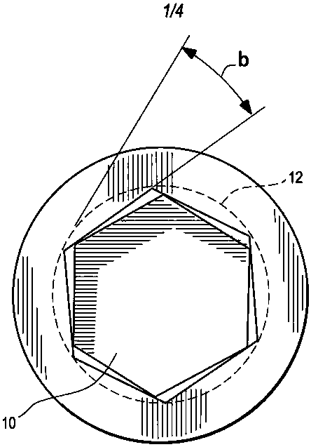
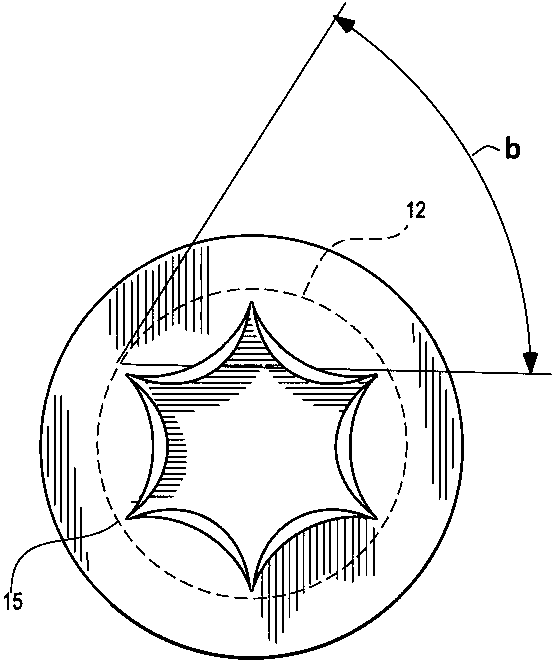
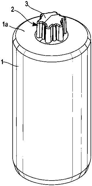
[0035] Such as Figure 2 to Figure 3 As shown, in a preferred embodiment of the present invention, a screw punch die includes a main body 1, a punch 2, and a cone 3, the main body 1 is a cylinder, and a plane 1a is provided at its top , the punch 2 is integrally formed with the main body 1...


PUM


Abstract

The invention discloses a die punch for manufacturing fasteners. The fasteners are screwdrivers, and the die punch is a stamping die for manufacturing the screwdrivers. The punch of the die comprisesa tapered outer edge, a plurality of ribs disposed around the outer edge and a beveled surface, and the beveled surface is arranged to remove burrs. The die punch can be used for forming various slotsincluding star-shaped or plum-shaped slots. The screwdrivers are more closely inserted into slots of screws to further enable the screws to be more firmly and smoothly screwed into a workpiece, and the occurrence of shaking, vibration and tilting is reduced.

Description

technical field [0001] The present invention relates to a die punch for manufacturing fasteners, in particular to a die punch for manufacturing fasteners with quincunx or star-shaped slots. Background technique [0002] Generally, to manufacture screws or screwdrivers, the metal wire will be drawn first, usually the metal wire will be stretched to a certain thickness, and then a punch will be used to make it into a screw or screwdriver with a screw head and a rod, and then a Rolling and rubbing dies form threads on the rod, and the screw head is usually formed by a stamping process, and the screw head will be stamped with a slot at the same time. The first stamping provides a slot positioning point to facilitate the second stamping, and the second stamping is the second stamping to form a slot in the head of the fastener , if the slot is well designed, a screwdriver bit can be safely and stably inserted and fitted into the slot so that the screwdriver bit can turn the faste...

Claims


Application Information

Patent Timeline
IPC IPC(8): B21D28/14
CPCB21D28/14
Inventor 陈鸿麟郭永裕麦可·强·罗斯
Owner 鸣达精工股份有限公司
Why Eureka
Try Eureka