
Continuous spring connected spring box type oven

A spring box, box-type technology, applied in the field of processing and manufacturing, can solve the problems of uneven heating between the middle and the edge, large smoke and unenvironmental protection, and large oven volume, etc., to achieve enhanced shaping effect, good shaping effect, and good working environment. Effect

Inactive Publication Date: 2018-12-25
宁波江北海梦机械有限公司
View PDF0 Cites 0 Cited by
  • Summary
  • Abstract
  • Description
  • Claims
  • Application Information

AI Technical Summary

Problems solved by technology

To keep it in a specific shape, the traditional method is mostly labor-intensive and the local smoke is not environmentally friendly. Due to the large volume of the special oven, it causes problems such as uneven heating in the middle and edges, local overheating and deformation, and also produces oily smoke and other problems.

Method used


Image

  • Continuous spring connected spring box type oven
  • Continuous spring connected spring box type oven
  • Continuous spring connected spring box type oven

Examples


Embodiment 1

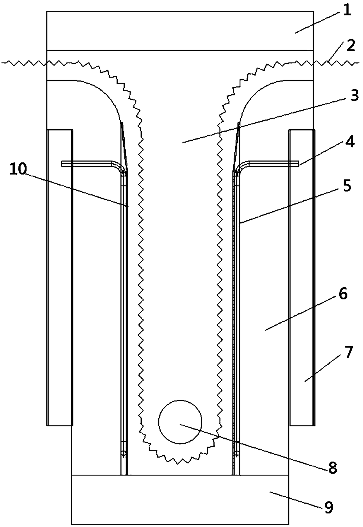
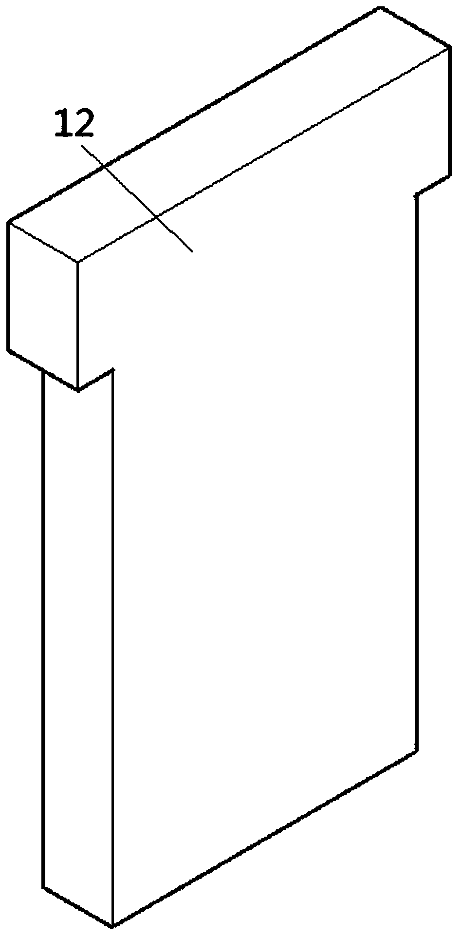
[0019] see figure 1 , figure 2 , Figure 4 , a box-type oven in the embodiment of the present invention, comprising a vertically arranged support installation plate 3, the upper end of the support installation plate 3 protrudes forward horizontally and is provided with an upper end insulation layer 1, and the lower end of the support installation rod faces toward the The front horizontal extension is provided with a lower end insulation layer 9, which is characterized in that the front end of the support installation plate 3 is vertically arranged with an installation insulation layer 6 symmetrically, and the opposite end faces of the installation insulation layer 6 on the left and right sides are all vertically arranged. There is a protective plate 10, and a spring 2 is provided in conjunction with the rotating drum 8, and the upper end of the installation insulation layer 6 is provided with a spring inlet and outlet in conjunction with the upper insulation layer 1, and the...

Embodiment 2

[0021] refer to image 3 , on the basis of Embodiment 1, electric heating tubes 5 are arranged on the installation insulation layer 6 opposite to the protective plate 10, and the upper ends of the electric heating tubes 5 are all protruded outwards to be provided with electric poles 4, and the protective plate 10 Cooperating with the electric heating tube 5, a number of uniform heat dissipation holes 11 are uniformly arranged, and the protection plate 10 is uniformly heated through the uniform heat dissipation holes 11, so that the spring is uniformly transformed, and the internal material is directionally transformed, and the shaping effect of the spring is strengthened.


PUM


Abstract

The invention relates to the fields of processing and manufacturing, and specifically relates to a continuous spring connected spring box type oven. The continuous spring connected spring box type oven comprises a vertically arranged supporting mounting plate; the upper end of the supporting mounting plate horizontally stretches out forwards and is provided with an upper end insulating layer; andthe lower end of the supporting mounting plate horizontally stretches out forwards and is provided with a lower end insulating layer. The continuous spring connected spring box type oven is characterized in that mounting insulating layers are symmetrically and vertically arranged at the front end of the supporting mounting plate; protective plates are vertically arranged on the opposite end facesof the mounting insulating layers on the left and right sides respectively; the oven is provided with a spring in cooperation with a rotating roller, and spring access ports are formed in the upper end insulating layer matched with the upper ends of the mounting insulating layers respectively. The device is compact in design, small in shape, little in smoke or free of smoke and good in operating environment during heating and baking, springs to be treated are uniformly heated and shaped in cooperation with the protective plates through electric heating tubes, the shaping effect is good, and the protective plates are uniformly heated through uniform heat dissipation holes, springs are uniformly converted, oriented conversion is carried out on internal substances, and the shaping effect of the springs is strengthened.

Description

technical field [0001] The invention relates to the field of processing and manufacturing, in particular to a wire-drawing and wire-drawing conjoined spring box-type oven. Background technique [0002] In the production process of springs, after the springs are produced, they are often baked in another oven to set the shape. To keep it in a specific shape, the traditional method is mostly labor-intensive and smoky and not environmentally friendly. Due to the large volume of the special oven, it causes problems such as uneven heating in the middle and edges, local overheating and deformation, and also produces oily smoke and other problems. [0003] In order to solve the above problems, the present invention is proposed. The device is compact in design and small in size. When heating and roasting, there is little or no smoke. The working environment is directly added to the machine for flow-through operation. Through the electric heating tube and the protection plate, the sp...

Claims


Application Information

Patent Timeline
IPC IPC(8): B21F99/00
CPCB21F99/00
Inventor 舒光平
Owner 宁波江北海梦机械有限公司
Learn More