
Sensor device with a radiation directing surface

a radiation-directing surface and sensor technology, applied in the field of sensing devices, can solve the problems of not being able to fit in most manufacturing application constraints, unable to meet the requirements of most applications, and being too large to achieve the effect of compact sensor device design and greater flexibility in the position of parts

Active Publication Date: 2010-05-18
OES
View PDF7 Cites 0 Cited by
  • Summary
  • Abstract
  • Description
  • Claims
  • Application Information

AI Technical Summary

Benefits of technology

"The patent describes a sensor device that uses a reflective surface to shape and direct a radiation field. The reflected radiation field has at least two parallel sides, which allows for a more compact design and flexibility in positioning a part within the device. The device also utilizes the entire length of the sensing element and is not subject to any distortion effects. The technical effects of this invention include space savings, flexibility in positioning a part within the device, and improved accuracy and precision in sensing."

Problems solved by technology

There are several disadvantages with such an arrangement.
This problem can become even more cumbersome if the parts are passed through different vertical planes (according to the drawing) within the viewing window 22.
Such an arrangement is not practical for most applications because the distances required to achieve appropriate focal points and the additional spacing required to accommodate the lens would render the device 20 too large to fit within most manufacturing application constraints.

Method used


Image

  • Sensor device with a radiation directing surface
  • Sensor device with a radiation directing surface

Examples


Embodiment Construction

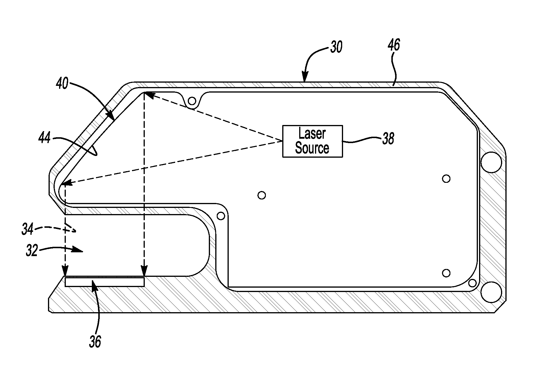
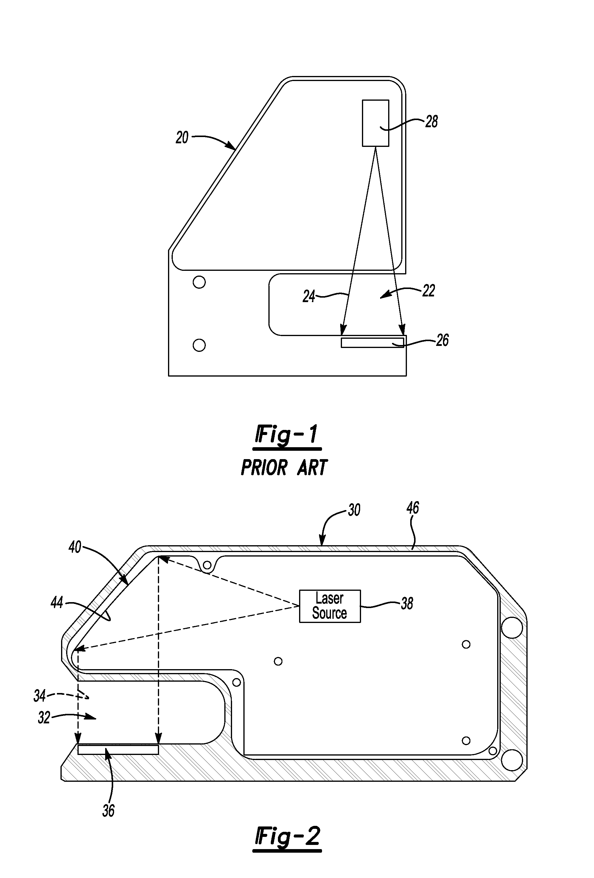
[0017]FIG. 2 schematically shows a sensor device 30 having a viewing window 32 through which a part such as a wire end may be passed. As the part passes through the viewing window 32, it interrupts a field of radiation 34 that otherwise irradiates a sensing element 36. In one example, the sensing element 36 comprises a CCD receiver and the radiation comprises light. Other types of radiation are used in some examples with correspondingly configured sensing elements. The amount of interruption of the radiation field 34, as detected by the sensing element 36, provides information for determining at least a characteristic or feature of an object within the viewing window 32. In one example, the sensor device 30 is useful for determining a part profile such as the profile of an end of a wire.

[0018]As can be appreciated from FIG. 2, the radiation field 34 incident on the sensing element 36 has at least two parallel sides projecting at a generally perpendicular angle relative to the orient...


PUM


Abstract

A sensor device includes a source of radiation and a reflective surface having a contour that directs radiation reflected from the surface along a field having at least two parallel sides. In a disclosed example, the reflective surface contour is at least partially curvilinear. A disclosed example includes a laser diode as the source of radiation and the reflective surface directs the reflected radiation in a direction that is generally perpendicular relative to a path that light follows as it emanates from the laser diode. The reflective surface in one example shapes the reflected radiation from a source that provides radiation along a path with obliquely oriented sides, the reflected radiation has at least two parallel sides. A disclosed sensor device is useful for measuring at least one feature of a part or object placed within a field of view of a sensing element that can detect the reflected radiation.

Description

CROSS REFERENCE TO RELATED APPLICATION[0001]This application claims priority to U.S. Provisional Application No. 60 / 669,329 which was filed on Apr. 7, 2005.FIELD OF THE INVENTION[0002]This invention generally relates to sensing devices. More particularly, this invention relates to devices for analyzing part profiles.DESCRIPTION OF THE RELATED ART[0003]A variety of sensing devices are known for use in manufacturing situations. For example, electrical assemblies that require hardwire connections typically rely upon particular qualities of the wire ends to ensure good connections. There are known sensors for monitoring the profile of the wire ends to determine quality and ensure better assembly.[0004]One such device is shown in U.S. Pat. No. 6,496,271. While the device shown in that patent represents a substantial improvement in the art, those involved in the industry are constantly striving to make improvements.[0005]FIG. 1 schematically shows one known arrangement of a sensing device...

Claims


Application Information

Patent Timeline
Patent Type & Authority Patents(United States)
IPC IPC(8): G01B11/24
CPCG01B11/24
Inventor NGO, KLETREEVE, MICHAELMARTINEZ, ERICA CHRISTINA
Owner OES
Learn More