Device for punching according to appointed depth on rubber product production line

A technology for rubber products and production lines, applied in metal processing and other directions, can solve problems such as the depth of holes that cannot be accurately punched, and the inability to punch holes in rubber tubes, and achieve the effect of accurately controlling the depth of holes

Active Publication Date: 2018-12-25
威海恒兴汽车配件有限公司
View PDF7 Cites 0 Cited by
  • Summary
  • Abstract
  • Description
  • Claims
  • Application Information

AI Technical Summary

Problems solved by technology

However, this equipment cannot punch holes on one side of the rubber tube, and cannot precisely punch holes.

Method used


Image

  • Device for punching according to appointed depth on rubber product production line
  • Device for punching according to appointed depth on rubber product production line
  • Device for punching according to appointed depth on rubber product production line

Examples


specific Embodiment approach 1

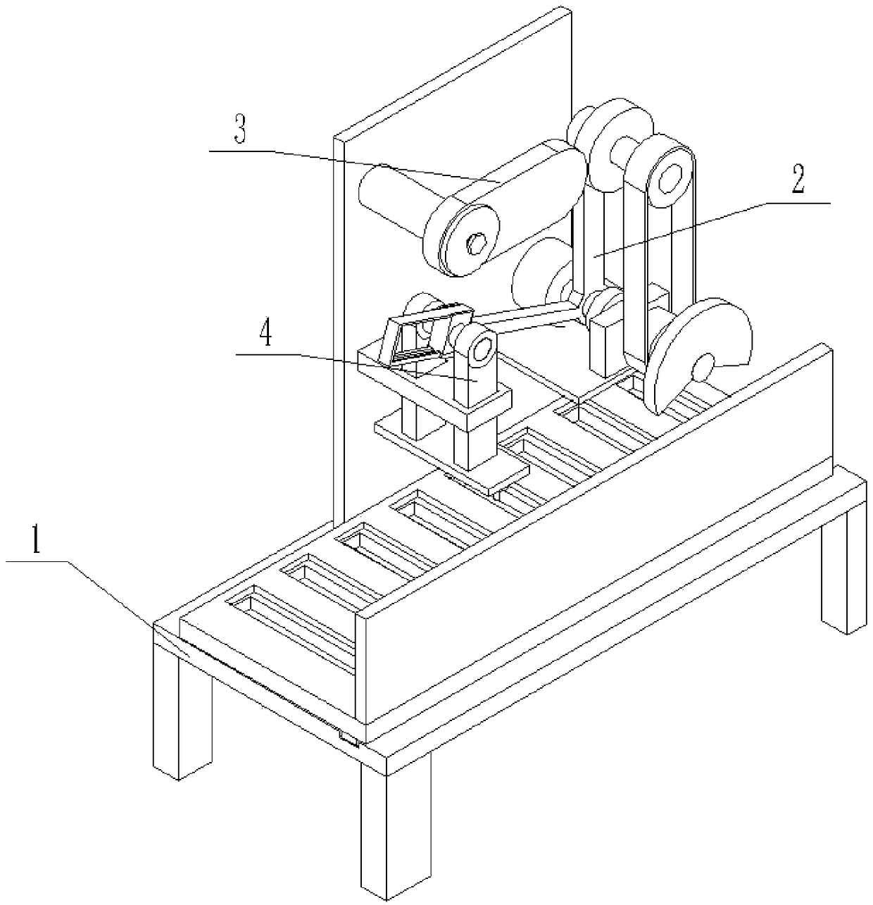
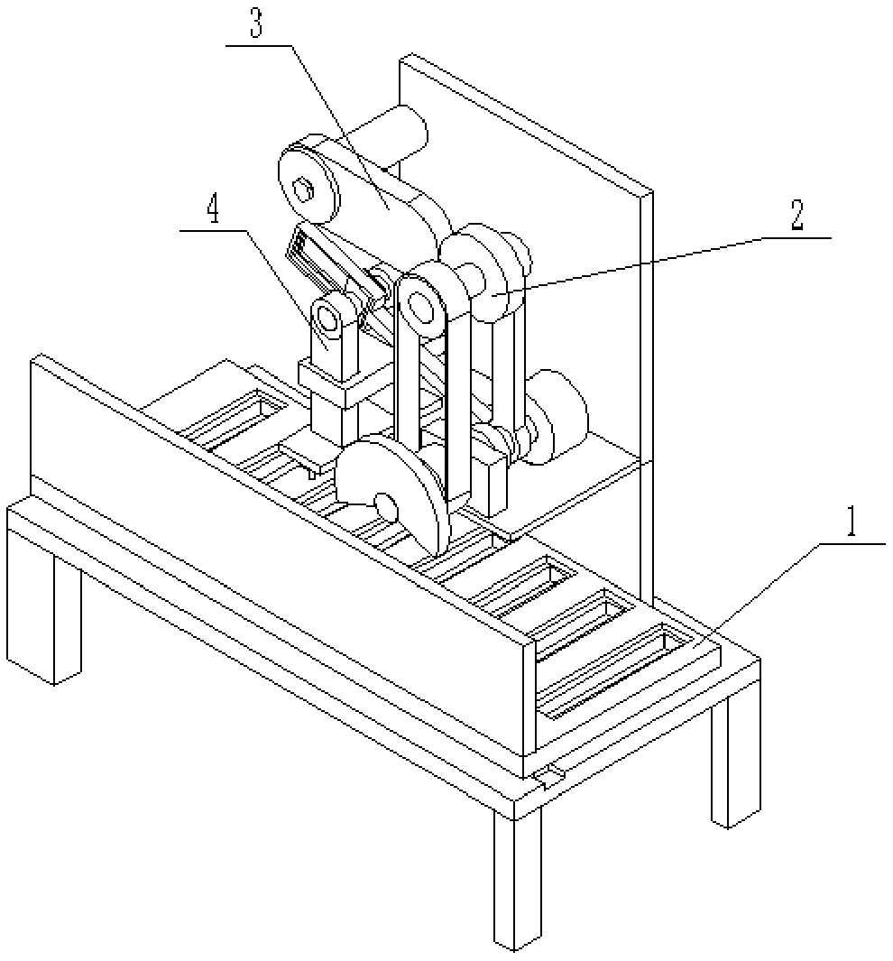
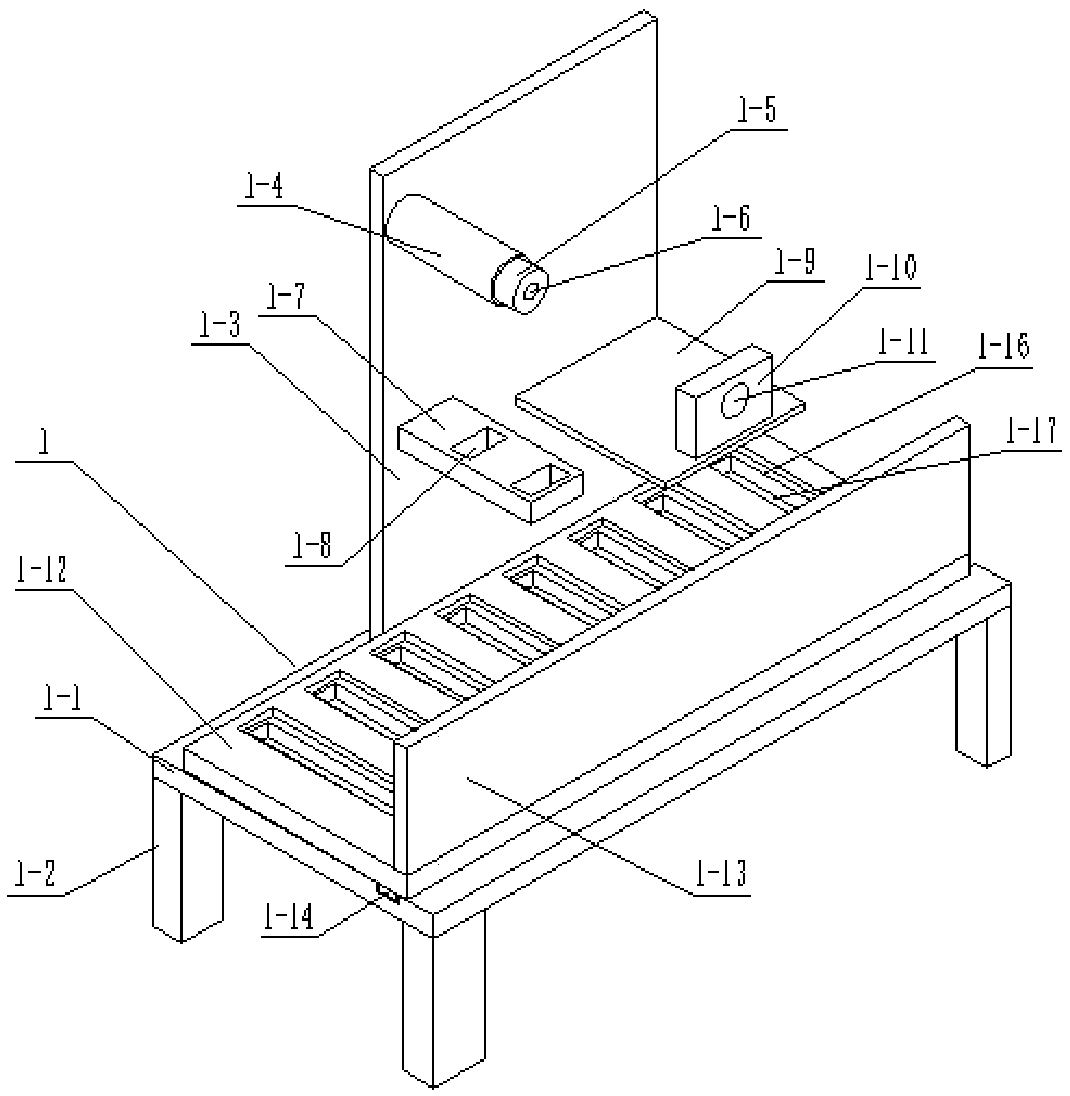
[0024] Such as Figure 1 to Figure 10 As shown, a device for punching holes at a specified depth on a rubber product production line, a device for punching holes at a specified depth on a rubber product production line, including a support base 1, a driver 2, an adjustment gear 3 and a drill Hole 4, characterized in that: the support base 1 includes a horizontal plate 1-1, four legs 1-2, a vertical plate 1-3, a fixed shaft 1-4, a rotating groove 1-5, and a threaded hole for replacement 1-6, left support plate 1-7, two through slots 1-8, right support plate 1-9, fixed plate 1-10, fixed round hole 1-11, loading plate 1-12, rack plate 1 -13, slider 1-14, chute 1-15, a plurality of object grooves 1-16 and a plurality of through grooves 1-17, four supporting legs 1-2 are respectively fixedly connected to the lower end of the horizontal plate 1-1 On the four bottom corners, the vertical plate 1-3 is fixedly connected to the front end of the horizontal plate 1-1, the front end of th...

specific Embodiment approach 2

[0026] Such as Figure 1 to Figure 10 As shown, this embodiment will further explain Embodiment 1. The adjustment gear 3 includes a replaceable oval gear 3-1, a rotating round hole 3-2, a plane bearing groove 3-3, a rotating end cover 3-4 and a tight Fixed bolt 3-5, rotating circular hole 3-2 is arranged on the left end of replaceable elliptical gear 3-1, plane bearing groove 3-3 is arranged on the rear end of replaceable elliptical gear 3-1, on the rotating end cover 3-4 Threaded holes are provided, the front end of the rotating end cover 3-4 is fixedly connected to the plane bearing, the rotating round hole 3-2 is clearance matched with the fixed shaft 1-4, and the fastening bolt 3-5 is threadedly connected to the threaded hole of the rotating end cover 3-4 And change threaded hole 1-6, plane bearing is rotatably connected in the plane bearing groove 3-3, and the right end of replaceable oval gear 3-1 is meshed transmission with driving gear 2-8.

specific Embodiment approach 3

[0027] Such as Figure 1 to Figure 10 As shown, this embodiment will further illustrate the second embodiment. The drill 4 includes a sliding block 4-1, a fixed rod 4-2, a left connecting rod 4-3, a right connecting rod 4-4, and a lower bottom plate. 4-5, a plurality of drilling motors 4-6 and a plurality of circular drilling blades 4-7, the sliding block 4-1 is slidably connected in the driving chute 2-11, and the fixed rod 4-2 is fixedly connected in the sliding block 4 -1, the left connecting rod 4-3 and the right connecting rod 4-4 are respectively fixedly connected to the left and right ends of the fixed rod 4-2, and the left connecting rod 4-3 and the right connecting rod 4-4 are gap-fitted in two respectively. In the through groove 1-8, the lower base plate 4-5 is fixedly connected to the lower ends of the left connecting rod 4-3 and the right connecting rod 4-4, and a plurality of drilling motors 4-6 are fixedly connected to the lower end of the lower base plate 4-5, ...


PUM


Abstract

The invention relates to the field of rubber punching, in particular to a device for punching according to an appointed depth on a rubber product production line. The device comprises a support base,a driver, an adjusting gear and a drilling machine; the support base comprises a transverse plate, four support legs, a vertical plate, a fixed shaft, a rotating groove, a replacement thread hole, a left support plate, two through grooves, a right support plate, a fixed plate, a fixed round hole, an object carrying plate, a rack plate, a slide block, a chute, multiple object holding tanks and multiple through grooves; the four support legs are fixedly connected to four bottom angles of the lower end of the transverse plate; the vertical plate is fixedly connected to the front end of the transverse plate; the front end of the fixed shaft is fixedly connected to the vertical plate; the rotating groove is formed in the fixed shaft; and the replacement thread hole is formed in the back end ofthe fixed shaft. The device has the following beneficial effects: the device can punch such rubber products as rubber pipes in batches; and meanwhile, the punching depth can be precisely controlled toprevent the through punching phenomenon of the rubber pipes.

Description

technical field [0001] The invention relates to the field of rubber punching, in particular to a device for punching holes at a specified depth on a rubber product production line. Background technique [0002] Patent No. CN201410091626.8 discloses a rubber sponge tube processing field, and discloses a rubber sponge tube punching machine. It includes a control system, a base frame, a splint assembly arranged on the base frame for clamping both sides of the rectangular cavity of the rubber sponge tube, a punching mechanism arranged at one end of the splint assembly, and a splint assembly for pulling the rubber sponge tube from the splint The end of the component away from the punching mechanism is transmitted to the transmission mechanism at the punching mechanism; the transmission mechanism is arranged below the splint assembly and is slidably connected with the base frame, and can be moved along the splint assembly. Longitudinal reciprocating movement. The rubber sponge t...

Claims


Application Information

Patent Timeline
IPC IPC(8): B26F1/16B26D7/26B26D5/02B26D5/08B26D7/06
CPCB26D5/02B26D5/08B26D7/06B26D7/2628B26F1/0015B26F1/0084B26F1/16
Inventor 董双喜
Owner 威海恒兴汽车配件有限公司
Why Eureka
Try Eureka