A device for punching holes at a specified depth on a rubber product production line
A technology for rubber products and production lines, applied in metal processing and other directions, can solve problems such as the depth of holes that cannot be accurately punched, and the inability to punch holes in rubber tubes, and achieve the effect of accurately controlling the depth of holes
- Summary
- Abstract
- Description
- Claims
- Application Information
AI Technical Summary
Problems solved by technology
Method used
Image
Examples
specific Embodiment approach 1
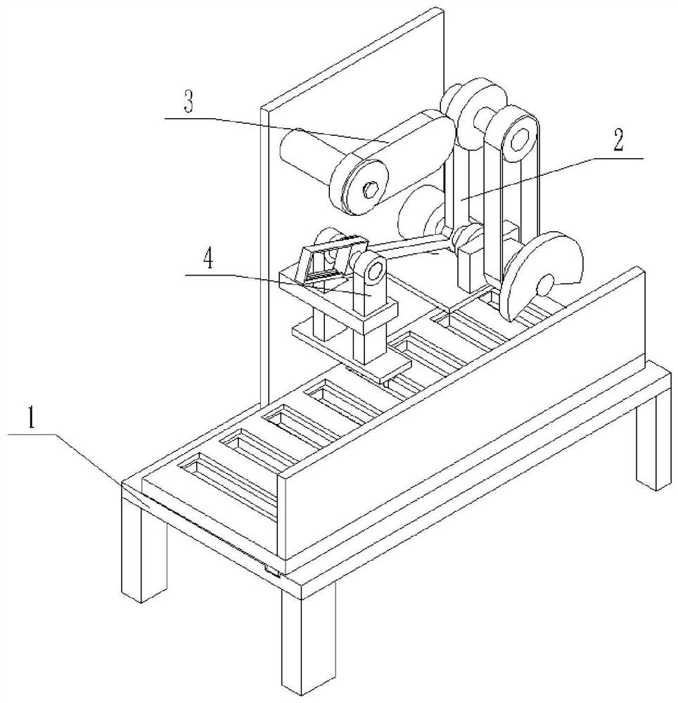
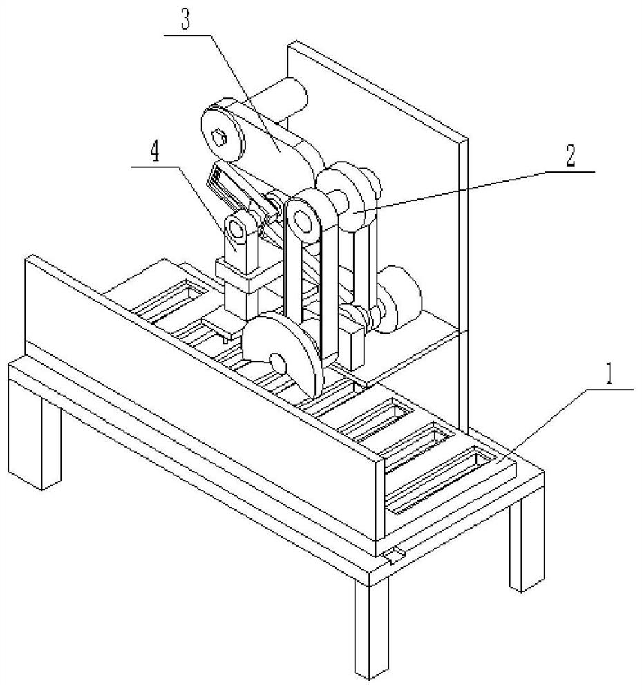
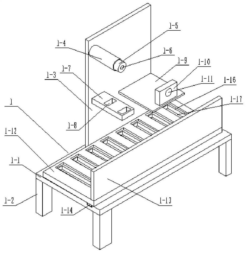
[0025] Such as Figure 1 to Figure 10 As shown, a device for punching holes at a specified depth on a rubber product production line, a device for punching holes at a specified depth on a rubber product production line, including a support base 1, a driver 2, an adjustment gear 3 and a drill Hole 4, characterized in that: the support base 1 includes a horizontal plate 1-1, four legs 1-2, a vertical plate 1-3, a fixed shaft 1-4, a rotating groove 1-5, and a threaded hole for replacement 1-6, left support plate 1-7, two through slots 1-8, right support plate 1-9, fixed plate 1-10, fixed round hole 1-11, loading plate 1-12, rack plate 1 -13, slider 1-14, chute 1-15, a plurality of object grooves 1-16 and a plurality of through grooves 1-17, four supporting legs 1-2 are respectively fixedly connected to the lower end of the horizontal plate 1-1 On the four bottom corners, the vertical plate 1-3 is fixedly connected to the front end of the horizontal plate 1-1, the front end of th...
specific Embodiment approach 2
[0028] Such as Figure 1 to Figure 10 As shown, this embodiment will further explain Embodiment 1. The adjustment gear 3 includes a replaceable oval gear 3-1, a rotating round hole 3-2, a plane bearing groove 3-3, a rotating end cover 3-4 and a tight Fixed bolt 3-5, rotating circular hole 3-2 is arranged on the left end of replaceable elliptical gear 3-1, plane bearing groove 3-3 is arranged on the rear end of replaceable elliptical gear 3-1, on the rotating end cover 3-4 Threaded holes are provided, the front end of the rotating end cover 3-4 is fixedly connected to the plane bearing, the rotating round hole 3-2 is clearance matched with the fixed shaft 1-4, and the fastening bolt 3-5 is threadedly connected to the threaded hole of the rotating end cover 3-4 And change threaded hole 1-6, plane bearing is rotatably connected in the plane bearing groove 3-3, and the right end of replaceable oval gear 3-1 is meshed transmission with driving gear 2-8.
specific Embodiment approach 3
[0030] Such as Figure 1 to Figure 10 As shown, this embodiment will further illustrate the second embodiment. The drill 4 includes a sliding block 4-1, a fixed rod 4-2, a left connecting rod 4-3, a right connecting rod 4-4, and a lower bottom plate. 4-5, a plurality of drilling motors 4-6 and a plurality of circular drilling blades 4-7, the sliding block 4-1 is slidably connected in the driving chute 2-11, and the fixed rod 4-2 is fixedly connected in the sliding block 4 -1, the left connecting rod 4-3 and the right connecting rod 4-4 are respectively fixedly connected to the left and right ends of the fixed rod 4-2, and the left connecting rod 4-3 and the right connecting rod 4-4 are gap-fitted in two respectively. In the through groove 1-8, the lower base plate 4-5 is fixedly connected to the lower ends of the left connecting rod 4-3 and the right connecting rod 4-4, and a plurality of drilling motors 4-6 are fixedly connected to the lower end of the lower base plate 4-5, ...
PUM
 Abstract
Description
Claims
Application Information
 - R&D
- Intellectual Property
- Life Sciences
- Materials
- Tech Scout
- Unparalleled Data Quality
- Higher Quality Content
- 60% Fewer Hallucinations
Browse by: Latest US Patents, China's latest patents, Technical Efficacy Thesaurus, Application Domain, Technology Topic, Popular Technical Reports.
© 2025 PatSnap. All rights reserved.Legal|Privacy policy|Modern Slavery Act Transparency Statement|Sitemap|About US| Contact US: help@patsnap.com


