
Anti-floating pile raft structure of pipe pile

An anti-floating pile and pipe pile technology, applied in the direction of foundation structure engineering, sheet pile wall, protection device, etc., to achieve the effect of improving bearing performance, reducing settlement and increasing frictional resistance

Inactive Publication Date: 2018-12-25
江苏中柢建设集团有限公司
View PDF4 Cites 0 Cited by
  • Summary
  • Abstract
  • Description
  • Claims
  • Application Information

AI Technical Summary

Problems solved by technology

However, the current pile valve structure still has certain deficiencies in integrity, bearing capacity and anti-floating effect, so there is an urgent need for a pipe pile anti-floating pile raft structure with high bearing capacity, strong integrity, and better anti-floating effect

Method used


Image

  • Anti-floating pile raft structure of pipe pile
  • Anti-floating pile raft structure of pipe pile
  • Anti-floating pile raft structure of pipe pile

Examples


Embodiment Construction

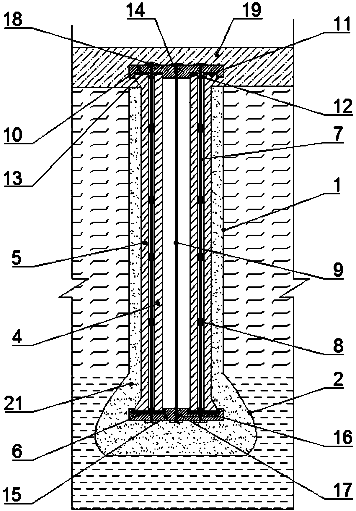
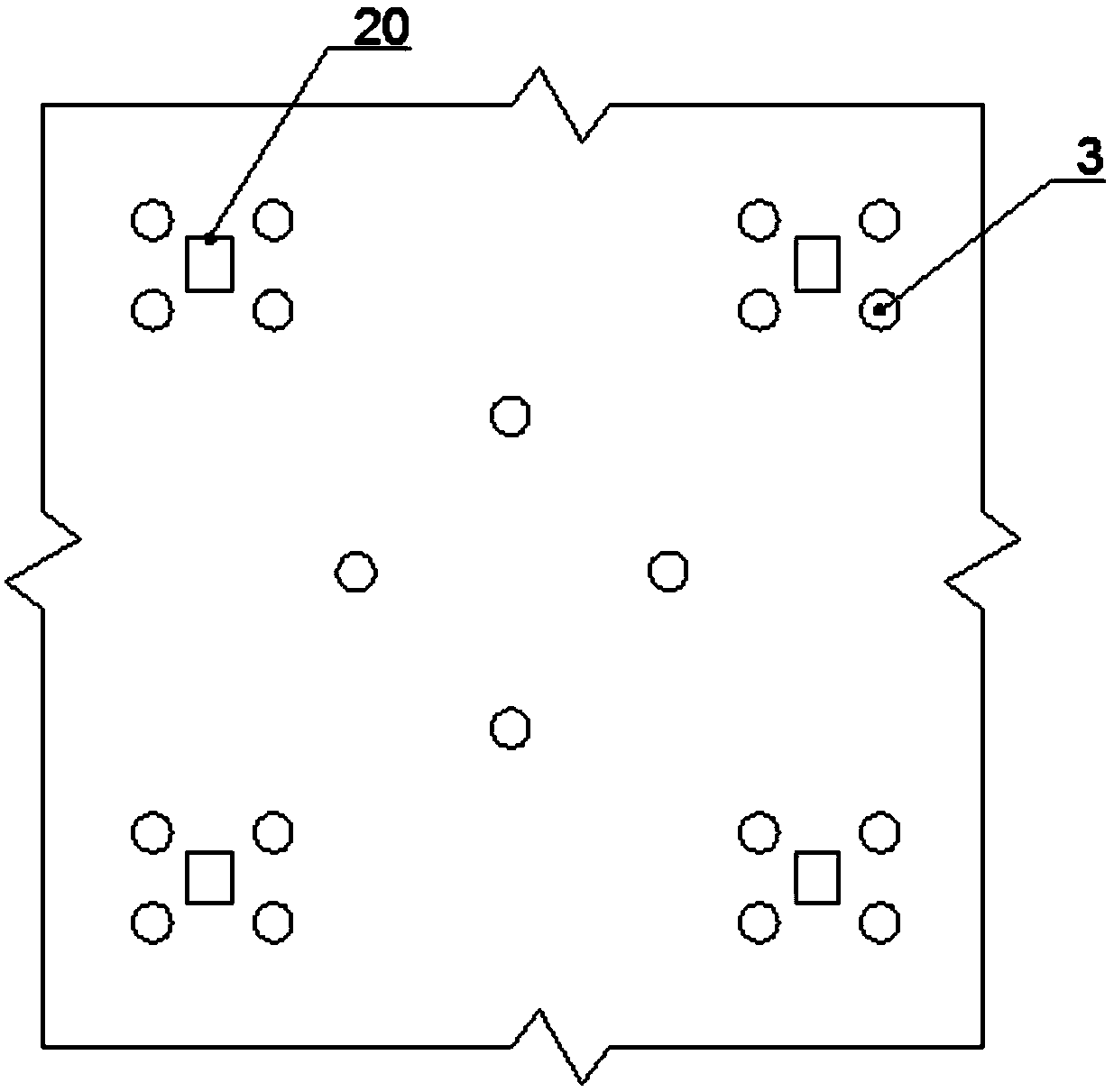
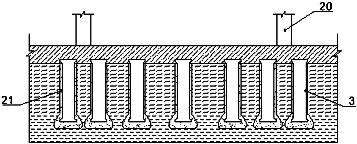
[0033] Such as Figure 1 to Figure 3 As shown, a pipe pile anti-floating pile raft structure includes a pile hole 1, an enlarged pile end 2 is arranged at the bottom of the pile hole 1, a pipe pile 3 is arranged in the pile hole 1, and a gap between the inner wall of the pile hole 1 and the outside of the pipe pile 3 The distance between the pile hole 1 and the pipe pile 3 is filled with a slurry solid 21, the material used for the slurry solid 21 is concrete, and the pipe pile 3 includes an inner cylinder 4 and an outer cylinder 5 distributed from the inside to the outside. The bottoms of the inner cylinder 4 and the outer cylinder 5 are connected by a sealing cap 6, a number of first anchor cables 7 are arranged between the inner cylinder 4 and the outer cylinder 5, and a plurality of annular rings 8 are arranged on the first anchor cables 7, and inside the inner cylinder 4 Several second anchor cables 9 are provided, the top end plate 10 is arranged on the top of the pipe p...


PUM


Abstract

The invention provides an anti-floating pile raft structure of a pipe pile, and belongs to the technical field of building engineering. The anti-floating pile raft structure comprises a pile hole, wherein the pipe pile is arranged in the pile hole; a space between the pile hole and the pipe pile is filled with a slurry solid; the pipe pile comprises an inner barrel and an outer barrel which are distributed in a spacing manner from inside to outside; the bottoms of the inner barrel and the outer barrel are connected through a sealing gap; a plurality of first anchor ropes are arranged between the inner barrel and the outer barrel; a plurality of annular rings are arranged on the first anchor ropes; a plurality of second anchor ropes are arranged in the inner barrel; a top end plate is arranged at the top of the pipe pile; a bottom end plate is arranged at the bottom of the pipe pile; the top end plate is embedded into a basic raft plate; and anchor rope fixing ends for fixing the firstanchor rope and the second anchor rope are arranged on the upper surface of the top end plate and the lower surface of the bottom end plate. The anti-floating pile raft structure of the pipe pile hasthe advantages of high bearing capacity, reduction of settlement, high integrality and high anti-floating capacity.

Description

technical field [0001] The invention belongs to the technical field of construction engineering, and in particular relates to a pipe pile anti-floating pile raft structure. Background technique [0002] With the rapid development of urban construction and the reduction of land resources, the downward trend of buildings is becoming more and more obvious. People also put forward higher requirements for the use of underground space, but the buoyancy of groundwater can easily cause the upper structure of buildings to tilt. , and even collapse, so the anti-floating problem of underground structures has also attracted increasing attention. [0003] The traditional anti-floating measures mainly include anti-floating anchors and prestressed anti-floating piles. The diameter of the anti-floating anchors is generally relatively small, and as the height of the building increases, the anti-floating anchors show many shortcomings in terms of bearing capacity. , while anti-floating piles...

Claims


Application Information

Patent Timeline
IPC IPC(8): E02D31/12E02D5/44E02D27/14
CPCE02D5/44E02D27/14E02D31/12E02D2250/0023
Inventor 还红年王晓武吉安辉蔡景龙王玉超侯前江
Owner 江苏中柢建设集团有限公司
Learn More