Floor drain sewer dredging device capable of instantly changing air pressure

An instantaneous change, air pressure technology, applied in waterway systems, water supply devices, drainage structures, etc., can solve the problems of high floor drain cost, easy blockage of sewer pipes, and inconvenient use of suction dredging equipment, and achieves convenient and fast use. Effort-saving effect

Active Publication Date: 2018-12-25
嘉兴昱天工业设计有限公司
View PDF7 Cites 6 Cited by
  • Summary
  • Abstract
  • Description
  • Claims
  • Application Information

AI Technical Summary

Problems solved by technology

[0004] Aiming at the deficiencies of the prior art, the present invention provides a floor drain sewer dredging device that instantly changes the air pressure, which solves the problem that the floor drain and the sewer pipes connected to it are easily blocked, the cost of refitting the floor drain is high, and the use of ordinary suction dredging equipment is inconvenient. question

Method used


Image

  • Floor drain sewer dredging device capable of instantly changing air pressure
  • Floor drain sewer dredging device capable of instantly changing air pressure
  • Floor drain sewer dredging device capable of instantly changing air pressure

Examples


Embodiment 1

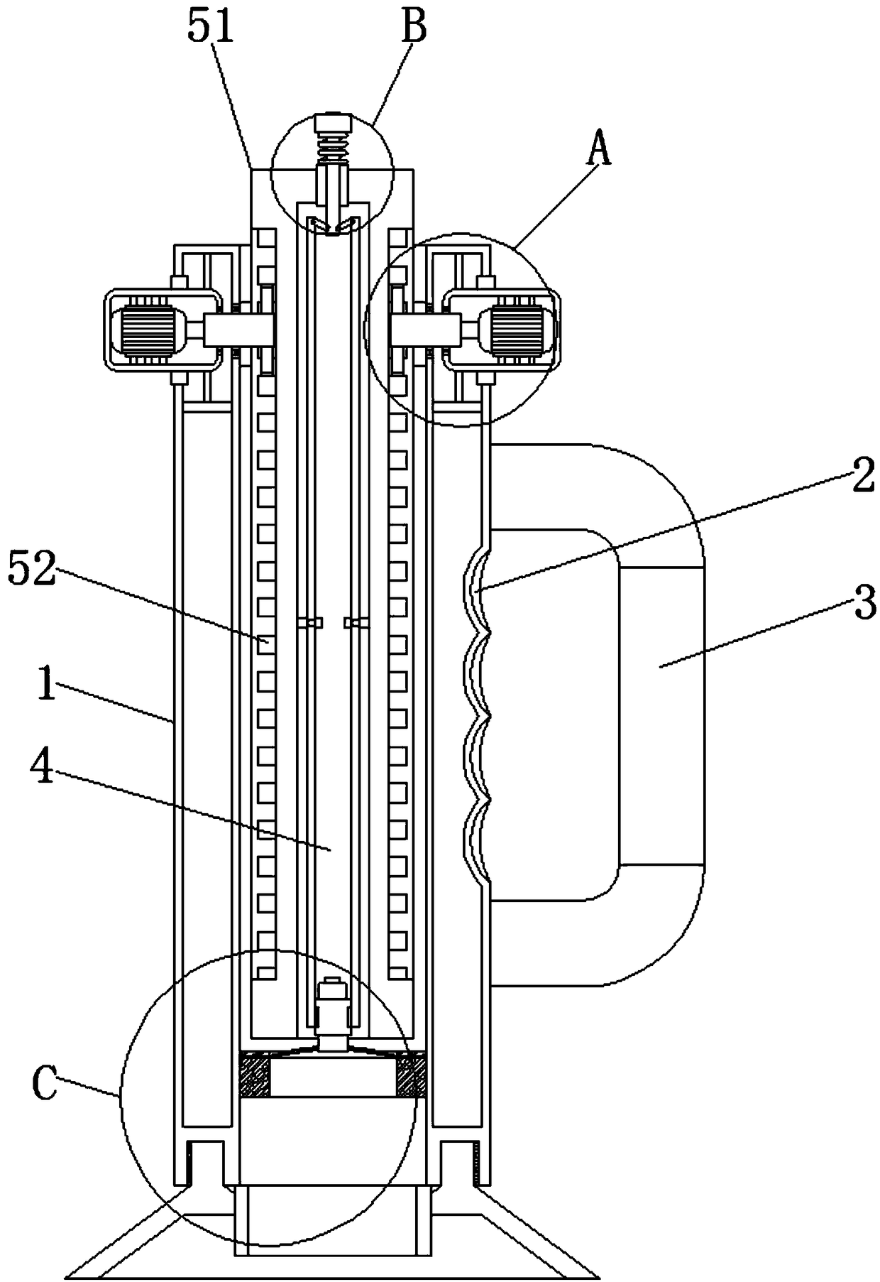
[0031] like Figure 1-5 As shown, a device for dredging floor drains and sewers that instantly changes the air pressure includes a support column 1, a finger mark groove 2 is provided in the middle of one side of the support column 1, and the finger mark groove 2 fits fingers, and the middle part of the support column 1 side is fixedly connected with a Handle 3, the surface of the handle 3 is provided with anti-slip lines, the finger mark groove 2 cooperates with the handle 3 to facilitate holding, the middle part of the support column 1 is provided with a through hole 4 connecting its top and bottom, and the inner cavity of the through hole 4 is provided with a pressure change Mechanism 5, the four sides of the bottom of the support column 1 are provided with annular thread grooves 6, and the bottom of the support column 1 is provided with a sealing connection mechanism 7.

Embodiment 2

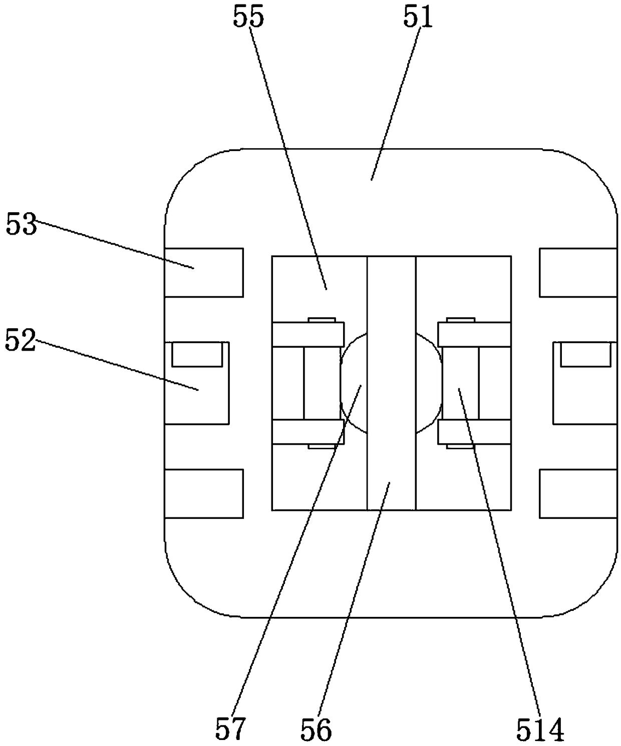
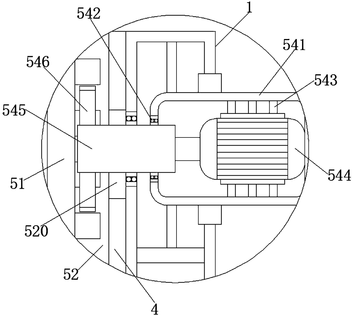
[0033]On the basis of Embodiment 1, the air pressure changing mechanism 5 includes a moving column 51, and the center of the moving column 51 is symmetrically provided with tooth grooves 52, and the front and back sides of the moving column 51 are symmetrically provided with chute 53, and the moving column 51 The tops on both sides are symmetrically provided with driving mechanisms 54, the middle of the bottom of the moving column 51 is provided with a moving groove 55, the bottom of the moving groove 55 inner cavity is provided with a support rod 56, and the center of the bottom of the support rod 56 is fixedly connected with a magnetic disk 57, and the magnetic disk 57 The bottom of the connecting cap 58 is adsorbed with a connecting cap 58, and the center of both sides of the connecting cap 58 is symmetrically provided with a card slot 59, and the center of the bottom of the connecting cap 58 is fixedly connected with a connecting block 521, and the bottom of the four sides o...

Embodiment 3

[0035] On the basis of Embodiments 1 and 2, the driving mechanism 54 includes a pressure-bearing box 541, and a second opening is opened in the middle of the opposite side of the pressure-bearing box 541 on both sides. The middle part of the top and bottom of the inner wall of the box 541 is symmetrically fixedly connected with a support frame 543, and the middle of the other side of the inner wall of the pressure box 541 is fixedly connected with a motor 544. An output shaft is extended, and the end of the output shaft of the motor 544 is fixedly connected with a rotating shaft 545 , and the end of the rotating shaft 545 away from the motor 544 is fixedly connected with a gear 546 .


PUM


Abstract

The invention discloses a floor drain sewer dredging device capable of instantly changing air pressure and relates to the technical field of floor drain sewer cleaning. The floor drain sewer dredgingdevice capable of instantly changing air pressure comprises a supporting column, wherein a finger mark groove is formed in the middle of one side of the supporting column, the middle of one side of the supporting column is fixedly connected with a handle, the middle of the supporting column is provided with a through hole communicated with the top and bottom of the supporting column, an air pressure changing mechanism is arranged in the inner cavity of the through hole, the four sides of the bottom of the supporting column are provided with annular threaded grooves, and the bottom of the supporting column is provided with a sealing connection mechanism. The floor drain sewer dredging device capable of instantly changing air pressure can achieve the effect of accumulating air mass and completing pipe dredging through an air pressure impact force, is convenient and efficient to use, does not make dirt to upwell and saves effort in use, and the problems are solved that a floor drain and asewer connected with the floor drain are possibly blocked, the cost for floor drain refitting is high, and a common suction-type dredging device is inconvenient to use.

Description

technical field [0001] The invention relates to the technical field of cleaning floor drains and sewers, in particular to a floor drain and sewer dredging device that instantly changes air pressure. Background technique [0002] The floor drain is an important interface connecting the drainage system with the indoor floor. In daily life, hair and debris will cause the floor drain and its connected sewer pipes to be blocked. If it is dredged, it will not only cost money to find a dredging worker, but also may carry out a major repair to the pipeline. The technology currently on the market, such as a floor drain with a hair filter device proposed by Chinese Patent No. CN107460941A, can achieve odor-proof, It is convenient to clean up large particles of impurities such as hair, but such a complicated technology leads to increased production costs and is not suitable for ordinary households. Traditional dredging equipment mostly uses suction to suck out the blockage, which smell...

Claims


Application Information

Patent Timeline
Patent Type & Authority Applications(China)
IPC IPC(8): E03F5/04E03C1/30
CPCE03C1/30E03F5/0407
Inventor 向开秀
Owner 嘉兴昱天工业设计有限公司
Why Eureka
Try Eureka