Garden lawn fallen leaf cleaning device

A technology for cleaning device and lawn, applied in lawn growth, gardening, grain treatment and other directions, can solve the problems of leaf wrinkle, low use efficiency, waste of space, etc., and achieve the effect of reducing occupied space, good effect and small occupied space.

Active Publication Date: 2018-12-28
浙江格新包装科技股份有限公司
View PDF11 Cites 12 Cited by
  • Summary
  • Abstract
  • Description
  • Claims
  • Application Information

AI Technical Summary

Problems solved by technology

Although this invention can play the effect of cleaning fallen leaves, there are still the following problems: 1. There is no device for compacting fallen leaves in this invention. Fallen leaves are generally more wrinkled, and many gaps will remain in the middle of stacking up, resulting in waste of space and reducing fallen leaves. 2. The leaves fall in autumn, so the efficiency of using the device is too low, and the invention has no other effect, so it will reduce its generalization
[0004] Except above-mentioned invention, the following problems also exist in other existing fallen leaves cleaning devices: the first, there is no equipment specially used for cleaning the fallen leaves on the lawn; its not working well

Method used


Image

  • Garden lawn fallen leaf cleaning device
  • Garden lawn fallen leaf cleaning device
  • Garden lawn fallen leaf cleaning device

Examples


Embodiment 1

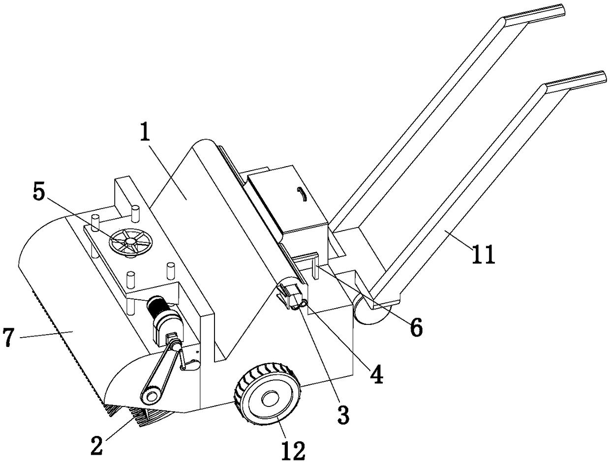
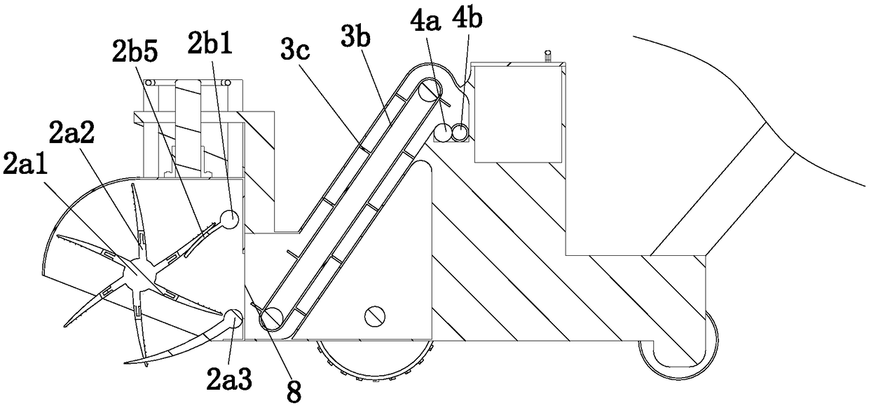
[0037] A garden and lawn leaf cleaning device, comprising a housing 1, a collecting mechanism 2, a conveying mechanism 3, a crushing mechanism 4, an adjusting mechanism 5 and a compacting mechanism 6, the upper end of the housing 1 is provided with a front shell 7, the front Both the shell 7 and the shell 1 are provided with a connecting port 8 for communicating the two, the collection mechanism 2 is installed on the lower end of the front shell 7, and the front shell 7 and the shell 1 are connected by an adjustment mechanism 5, so The conveying mechanism 3 is located between the collecting mechanism 2 and the crushing mechanism 4, and the rear end of the housing 1 is provided with two collecting chambers 9, both of which are located below the crushing mechanism 4, and the compacting mechanism 6 There are two, two compaction mechanisms 6 are respectively arranged in two collection chambers 9, the collection mechanism 2 includes a collection assembly 2a and a blocking assembly 2...

Embodiment 2

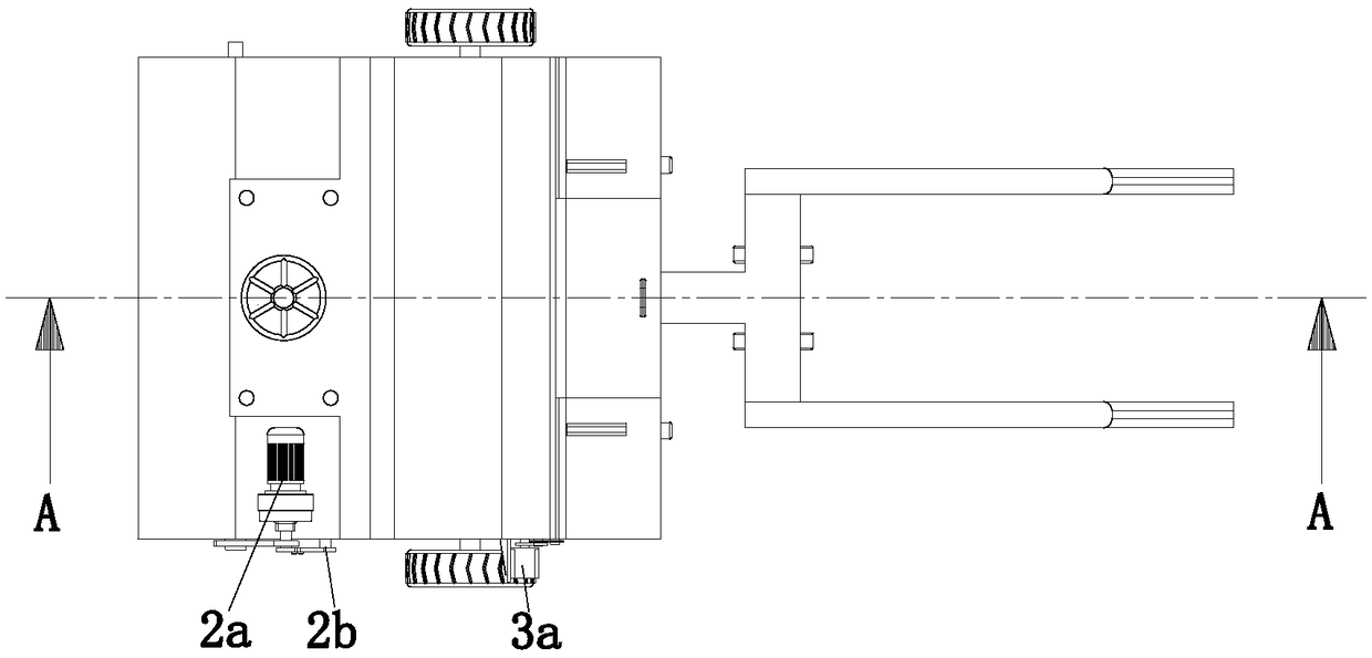
[0047] The collection assembly 2a includes a collection shaft 2a1, several mounting plates 2a2 and a shovel shaft 2a3, both ends of the collection shaft 2a1 are rotatably connected to the front shell 7, and several Mounting plate 2a2, the upper end of the front shell 7 is provided with a drive motor 2a4, the front end of the drive motor 2a4 is provided with a reducer 2a5, the output end of the reducer 2a5 is provided with a drive gear 2a6, and the collecting shaft 2a1 One end of the drive gear 2a7 is provided with a driven gear 2a7, and the driving gear 2a6 and the driven gear 2a7 are connected by a chain transmission. Both ends of the shoveling shaft 2a3 are fixedly connected with the front shell 7, and the The side wall is provided with several shoveling teeth 2a8 arranged at equal intervals, and the shoveling teeth 2a8 are arc-shaped, and each of the mounting plates 2a2 is provided with a cutting edge 2a11; by pushing the material on the mounting plate 2a2 Rake 2a9 is repla...


PUM


Abstract

The invention relates to the field of garden machines and in particular to a garden lawn fallen leaf cleaning device. The garden lawn fallen leaf cleaning device comprises a housing, a collecting mechanism, a conveying mechanism, a crushing mechanism, an adjusting mechanism and compacting mechanisms. The upper end of the housing is provided with a front housing. The front housing and the housing are provided with connecting ports which are used for communicating with two parties. The collecting mechanism is installed at the lower end of the front housing. The front housing and the housing areconnected through the adjusting mechanism. The conveying mechanism is positioned between the collecting mechanism and the crushing mechanism. The rear end of the housing is provided with two collecting cavities. The two collecting cavities are positioned below the crushing mechanism. There are two compacting mechanisms. The two compacting mechanisms are installed in the two collecting cavities. The collecting mechanism comprises a collecting component and a material blocking component. The material blocking component is positioned beside the collecting component. The beneficial effect is thatthe garden lawn fallen leaf cleaning device can be used as a mower or used as a fallen leaf cleaning machine, has more functions, has the better fallen leaf collecting effect and is capable of storingmore fallen leaves.

Description

technical field [0001] The invention relates to the field of garden machinery, in particular to a device for cleaning fallen leaves on garden lawns. Background technique [0002] In autumn and winter, the leaves of deciduous trees will gradually fall off, causing the grass to be covered with fallen leaves, and the fallen leaves will become dry after being exposed to the sun and air-dried, and are flammable. Therefore, if the fallen leaves are not handled in time, there will be fire hazards. Security risks. [0003] Chinese patent No. CN106677103B discloses a deciduous sweeper, including a chassis, on which a drive system and a total dust box are arranged, and a front wheel and a rear wheel are arranged below the chassis, and the rotation of the front wheels is driven by the drive system. The position between the front wheel and the rear wheel is provided with a cleaning main brush, and a leaf collection device is also provided at the front end of the front wheel. The leaf c...

Claims


Application Information

Patent Timeline
Patent Type & Authority Applications(China)
IPC IPC(8): A01G20/43A01D43/10A01D43/077A01D43/00B02C18/14B30B9/30
CPCA01D43/006A01D43/077A01D43/10A01G20/43B02C18/0084B02C18/14B02C2201/066B30B9/30
Inventor 高月民袁福德李万青
Owner 浙江格新包装科技股份有限公司
Why Eureka
Try Eureka