
Splicing comb and manufacturing method thereof

A manufacturing method and comb technology, which are applied in hair combs, clothing, hairdressing equipment, etc., can solve the problems of waste, scraps cannot meet the size requirements, cannot be used, etc., and achieve the effect of simple operation principle and simple structure.

Inactive Publication Date: 2018-12-28
付书艺
View PDF10 Cites 2 Cited by
  • Summary
  • Abstract
  • Description
  • Claims
  • Application Information

AI Technical Summary

Problems solved by technology

[0003] At present, in the production and processing process of combs, it is first necessary to cut a number of blanks from larger raw materials, and then process the blanks to obtain combs. After cutting the blanks from the raw materials, a large number of blanks will remain The leftovers and short joints that are smaller than the design size of the comb, these leftovers cannot be used because they do not meet the size requirements, and can only be discarded, resulting in a lot of waste, which is seriously inconsistent with the concept of a conservation-oriented society advocated by the state

Method used


Image

  • Splicing comb and manufacturing method thereof
  • Splicing comb and manufacturing method thereof
  • Splicing comb and manufacturing method thereof

Examples


Embodiment Construction

[0038] The following will clearly and completely describe the technical solutions in the embodiments of the present invention with reference to the accompanying drawings in the embodiments of the present invention. Obviously, the described embodiments are only some, not all, embodiments of the present invention. Based on the embodiments of the present invention, all other embodiments obtained by persons of ordinary skill in the art without creative efforts fall within the protection scope of the present invention.

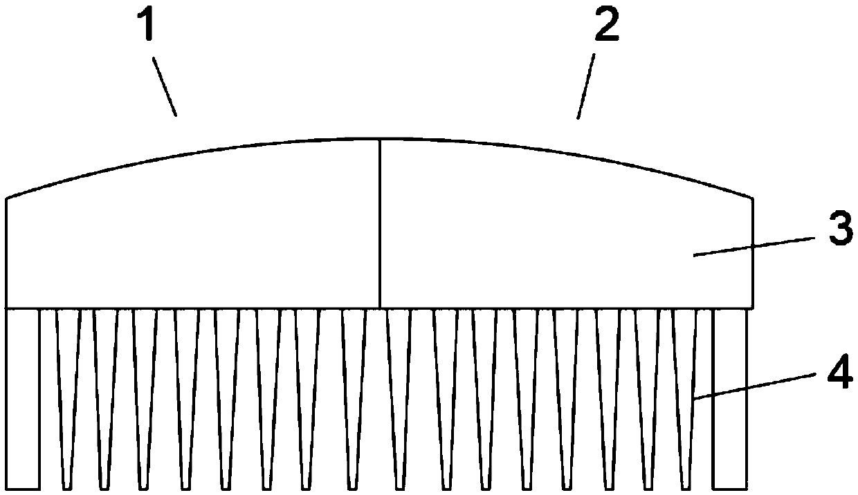
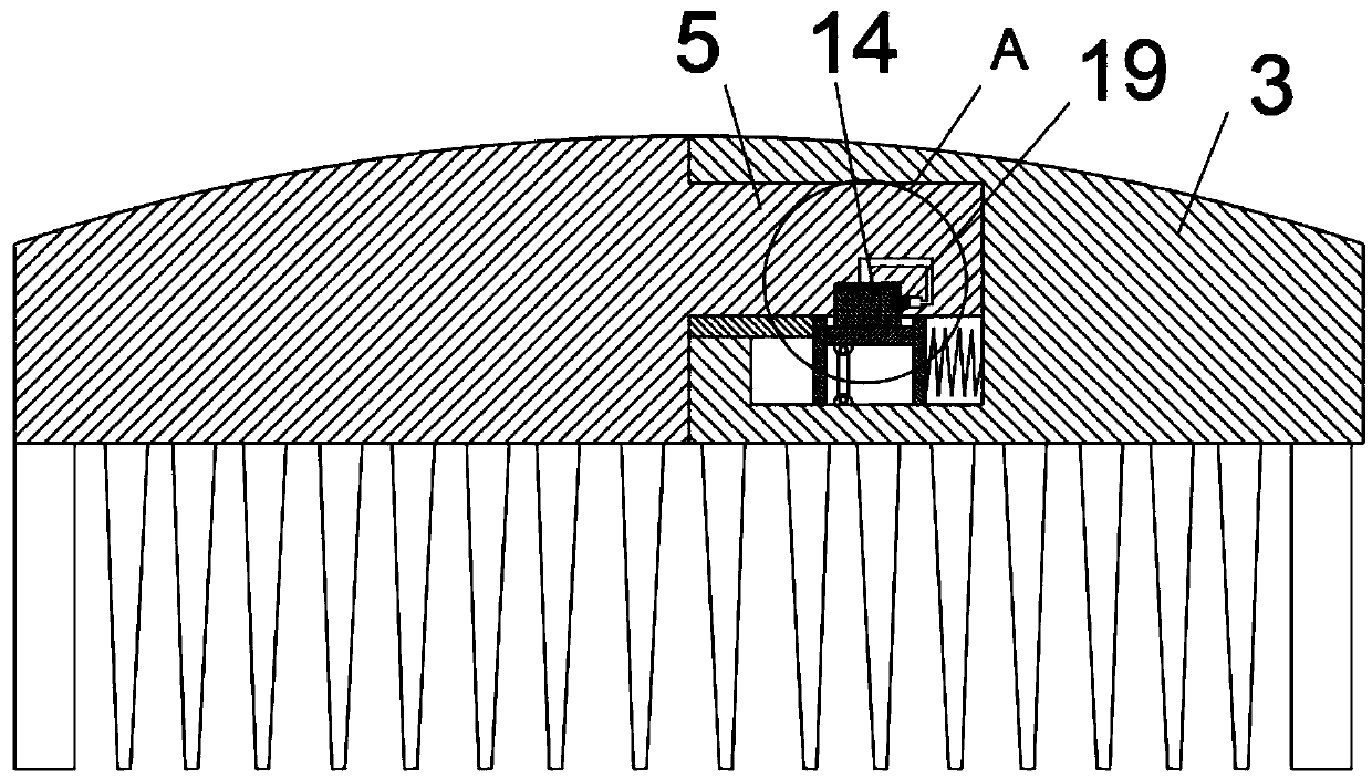
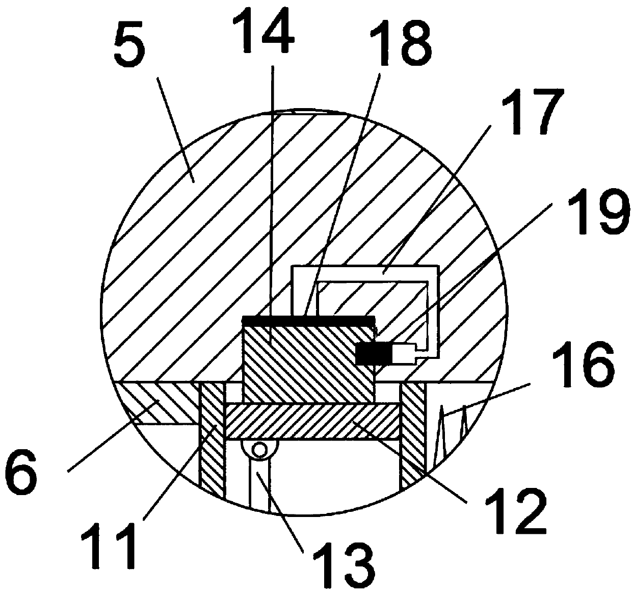
[0039] Such as Figure 1-7 said, figure 1 It is a schematic appearance diagram of a specific embodiment of a splicing comb of the present invention; figure 2 It is a schematic diagram of the connection structure of a specific embodiment of a splicing comb of the present invention; image 3 for the invention figure 2 The enlarged schematic diagram of A in the middle; Figure 4 It is a structural schematic diagram of the first splicing body of the present inven...


PUM


Abstract

The invention provides a splicing comb which comprises a first splicing body and a second splicing body. Each of the first splicing body and the second splicing body is provided with a comb beam and comb teeth, an inserting piece is arranged on a splicing face of the comb beam of the first splicing body in a protruding manner, a pushing piece is fixed below the inserting piece, an inserting grooveis formed in the lower surface of the inserting piece, an airway is arranged inside the inserting piece, an airbag communicated with one end of the airway is arranged in the inserting groove, and theother end of the airway is movably connected with a piston rod penetrating the side wall of the inserting groove; an inserting hole corresponding to the inserting piece is formed in the second splicing body, a movable sliding shell corresponding to the pushing piece is arranged in the inserting hole, an inserting block capable of moving up and down and corresponding to the inserting groove is arranged in the sliding shell, a fixing hole matched with the piston rod is formed in the side face of the inserting block, and air pressure in the airway can push the piston rod to enter the fixing holewhen the inserting block squeezes the airbag. The splicing comb is simple in structure and splicing operation principle, and leftover material waste caused by the fact that blanks are directly cut out on raw materials with big size for processing in the prior art can be avoided.

Description

technical field [0001] The invention relates to the technical field of dressing utensils, in particular to a spliced ​​comb and a manufacturing method thereof. Background technique [0002] The comb is a dressing utensil for arranging hair. The one with sparse teeth is called "comb", and the one with dense teeth is called "comb". It is widely used in combing and arranging hair. [0003] At present, in the production and processing process of combs, it is first necessary to cut a number of blanks from larger raw materials, and then process the blanks to obtain combs. After cutting the blanks from the raw materials, a large number of blanks will remain Leftovers and short joints that are smaller than the design size of the comb, these leftovers cannot be used because they do not meet the size requirements, and can only be discarded, resulting in a lot of waste, which is seriously inconsistent with the concept of a conservation-oriented society advocated by the state. [0004]...

Claims


Application Information

Patent Timeline
Patent Type & Authority Applications(China)
IPC IPC(8): A45D24/04A45D24/10
CPCA45D24/04A45D24/10
Inventor 付书艺
Owner 付书艺
Learn More