Circular gantry robot moving system

A mobile system and robot technology, applied in the field of robotics, can solve problems such as large-span mobile operations, size changes, and robot arm spans not meeting applicable requirements, to achieve the effect of ensuring accuracy and avoiding size changes

Pending Publication Date: 2018-12-28
斯图加特航空自动化(青岛)有限公司
View PDF0 Cites 5 Cited by
  • Summary
  • Abstract
  • Description
  • Claims
  • Application Information

AI Technical Summary

Problems solved by technology

[0002] In the welding and cutting processes of the existing circular workpieces, most of the gantry robots are used. At present, due to the structural limitations of the gantry robots, the arm span required by the robot when welding some special workpieces cannot meet the applicable requirements. , and there are obvious defects, such as dimensional changes

Method used


Image

  • Circular gantry robot moving system
  • Circular gantry robot moving system
  • Circular gantry robot moving system

Examples


Embodiment Construction

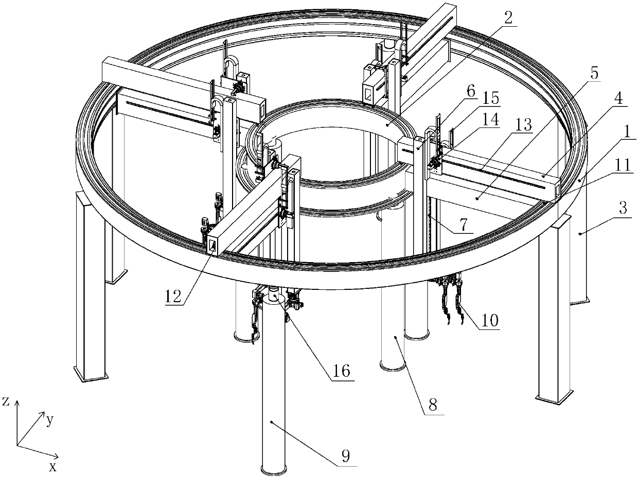
[0021] Due to the dimensional changes caused by the temperature difference in the working environment of the existing gantry-type equipment in the welding and cutting of circular workpieces, it is difficult to ensure the accuracy of each axis in different situations. At the same time, the working stroke of the robot or other end-effectors The request cannot be met.

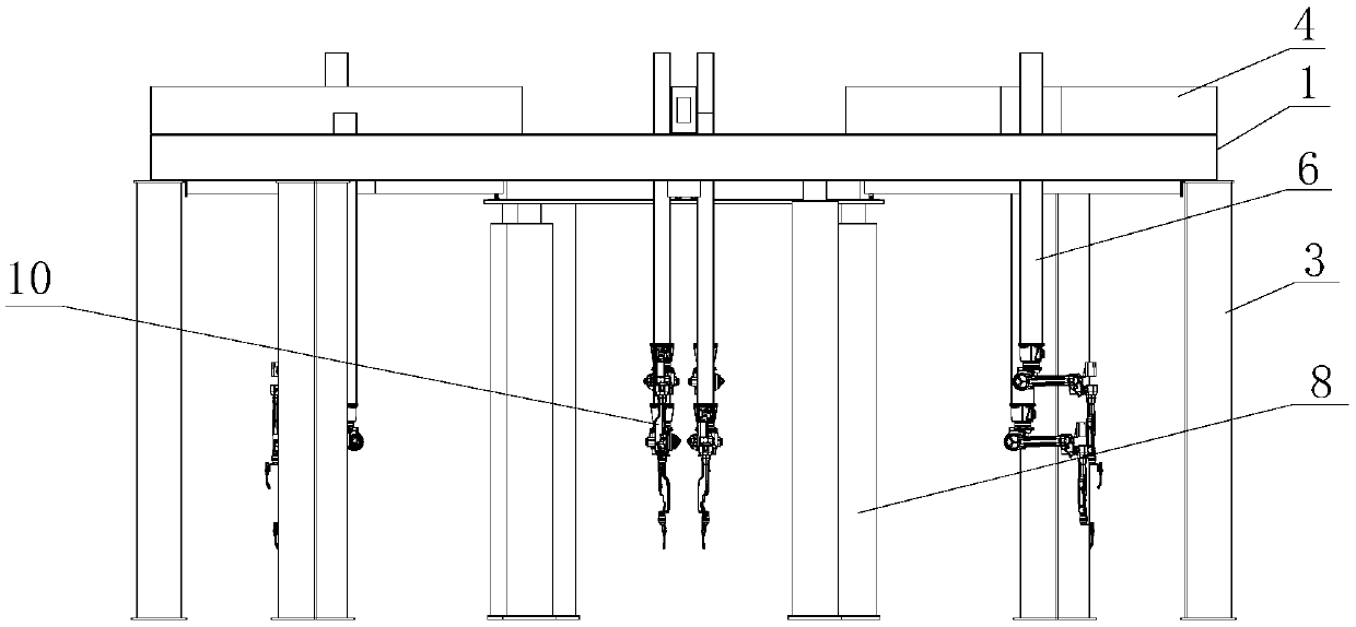
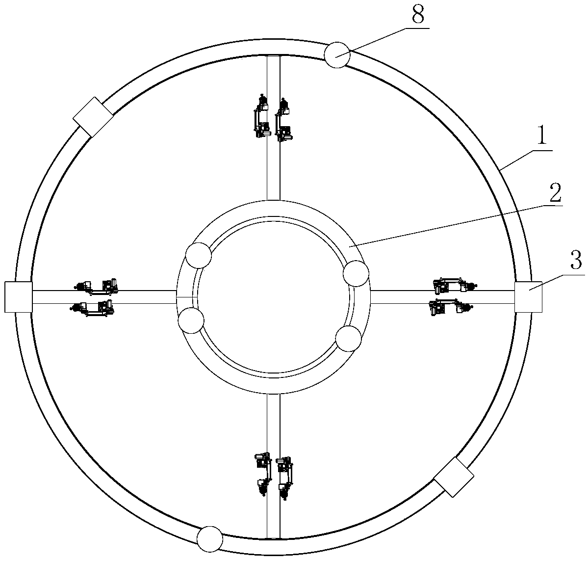
[0022] Aiming at the problems existing in the prior art, the present invention adopts an XYZ three-axis traveling mechanism, wherein the X-axis is designed in a ring shape, which avoids the size change caused by the temperature difference in the working environment, and the Y-axis and Z-axis change synchronously with the workpiece, thus ensuring that each The precision of the axes in different situations.

[0023] In order to make the object, technical solution and advantages of the present invention clearer, the present invention will be described in detail below in conjunction with the accompanying drawings and ...


PUM


Abstract

The invention belongs to the technical field of robots and particularly relates to a circular gantry robot moving system. The circular gantry robot moving system comprises a circular outer beam, fixing stand columns, robot executing terminals, a lifting inner circular module, beam modules and Z-axis modules, wherein the circular outer beam is supported by the fixing stand column; the inside of thecircular outer beam are circumferentially provided with a plurality of the beam modules, one end of every beam module is slidingly connected with the circular outer beam, the other end of the beam module extends towards the center of the circular outer beam, and the beam modules can move circumferentially; the lifting inner circular module is arranged inside the circular outer beam for support the other ends of the beam modules; every beam module is provided with a corresponding Z-axis module capable of moving radially; the robot executing terminals are vertically movably arranged on the Z-axis module. The circular gantry robot moving system can ensure the precision of axes under different conditions guarantee that the executing mechanism are mounted at the tail end the Z-axis, and through coordination in three directions, achieving movement to any position within a walking space range.

Description

technical field [0001] The invention belongs to the technical field of robots, in particular to an annular gantry type robot moving system. Background technique [0002] In the welding and cutting processes of the existing circular workpieces, most of the gantry robots are used. At present, due to the structural limitations of the gantry robots, the arm span required by the robot when welding some special workpieces cannot meet the applicable requirements. , and there are obvious defects, such as dimensional changes caused by temperature differences in the working environment, it is difficult to guarantee the accuracy of each axis under different conditions. The existing gantry-type robot welding cannot perform large-span mobile operations, the working area of ​​the robot is limited, and the working stroke of the robot or other end effectors cannot meet the requirements. Contents of the invention [0003] In view of the above problems, the object of the present invention ...

Claims


Application Information

Patent Timeline
IPC IPC(8): B25J5/04B25J9/12
CPCB25J5/04B25J9/1035B25J9/12
Inventor 肖林薛海涛杜金凤初建松
Owner 斯图加特航空自动化(青岛)有限公司
Why Eureka
Try Eureka