Cutting device for packaging box

A cutting device and packaging box technology, applied in metal processing and other directions, can solve the problems of harming the health of workers, causing movement, and reducing the yield of sheet materials, and achieving the effect of avoiding product quality and preventing movement.

Inactive Publication Date: 2018-12-28
苏州凤羽包装材料有限公司
View PDF0 Cites 1 Cited by
  • Summary
  • Abstract
  • Description
  • Claims
  • Application Information

AI Technical Summary

Problems solved by technology

[0002] As the name suggests, the packaging box is the box used to package the product. It can be classified according to the material, such as: paper box, iron box, wooden box, cloth box, leather box, acrylic box, corrugated box, PVC box, etc., and the packaging box is produced It needs to be cut during the process. When the blister packaging box is produced, first cut the PVC tape or PP tape into the required size sheet, and then cut the PVC tape or PP tape into the required size sheet. Generally all are finished by sheet material cutting device, and the sheet material cutting device on the existing market generally comprises frame, is positioned at the motor on the frame, is driven by the disc-shaped blade of motor, is positioned at the strip stable box below blade block; the motor is fixed on the motor mounting frame, the motor mounting frame is fixed on the rotating shaft, one end of the rotating shaft has a handle, and by pulling the handle, the rotating shaft swings up and down on the motor mounting frame to realize the cutting of the strip, During the use of this type of structure, sheets of different sizes require blades of different diameters and strips of different widths to stabilize the box, making the entire sheet cutting device bulky and heavy. As the time goes by, there will be movement, which will reduce the yield of the sheet, and the debris or flying dust generated during the cutting process will be scattered everywhere, endangering the health of the staff

Method used


Image

  • Cutting device for packaging box
  • Cutting device for packaging box
  • Cutting device for packaging box

Examples


Embodiment Construction

[0017] The preferred embodiments of the present invention will be described below in conjunction with the accompanying drawings. It should be understood that the preferred embodiments described here are only used to illustrate and explain the present invention, and are not intended to limit the present invention.

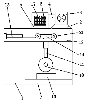
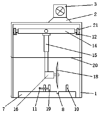
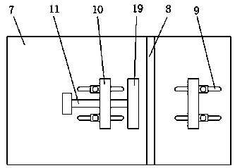
[0018] Such as Figure 1-3 As shown, a cutting device for a packaging box includes a cabinet body 1, a dust collection cover 2 is fixedly connected to the top of the cabinet body 1, an exhaust fan 3 is installed on the top of the dust collection cover 2, and the exhaust fan 3 passes through The dust collection cover 2 communicates with the inner cavity of the cabinet body 1, and can suck away debris or flying dust generated by cutting sheets in the cabinet body 1, so as to avoid being sucked into the lung cavity by the staff and endanger the health of the staff. The exhaust fan 3 One side is connected with an exhaust pipe 4, and one end of the exhaust pipe 4 is conn...


PUM


Abstract

The invention relates to a cutting device for a packaging box. The cutting device comprises a cabinet. The top of the cabinet is fixedly connected with a dust collection cover. An exhaust fan is mounted at the top of the dust collection cover, and communicates with an inner cavity of the cabinet through the dust collection cover. One side of the exhaust fan is connected with an exhaust pipe, and one end of the exhaust pipe is connected with a dust collection box. Exhaust outlets are formed in the two sides of the dust collection box correspondingly, and the bottom of the inner cavity of the cabinet is fixedly connected with a bottom plate. A groove is formed in the top of the bottom plate, and strip-shaped wire holes are symmetrically formed in the two sides of the groove. The cutting device is simple in structure and convenient to operate, and chippings or flying dust generated during sheet cutting in the cabinet can be sucked away to avoid the situation that the chippings or the flying dust is sucked by workers into lung cavities and consequently harms body health of the workers; the chippings or the flying dust discharged by the exhaust fan can be filtered and collected to avoidthe situation that the chippings or the flying dust is discharged into air and consequently pollutes the environment; and the positions of sheets with different sizes can be fixed, the sheets are prevented from moving during cutting, and thus the influences on the product quality are avoided.

Description

technical field [0001] The invention relates to a cutting device for a packaging box, which belongs to the field of packaging box production equipment. Background technique [0002] As the name suggests, the packaging box is the box used to package the product. It can be classified according to the material, such as: paper box, iron box, wooden box, cloth box, leather box, acrylic box, corrugated box, PVC box, etc., and the packaging box is produced It needs to be cut during the process. When the blister packaging box is produced, first cut the PVC tape or PP tape into the required size sheet, and then cut the PVC tape or PP tape into the required size sheet. Generally all are finished by sheet material cutting device, and the sheet material cutting device on the existing market generally comprises frame, is positioned at the motor on the frame, is driven by the disc-shaped blade of motor, is positioned at the strip stable box below blade block; the motor is fixed on the mo...

Claims


Application Information

Patent Timeline
Patent Type & Authority Applications(China)
IPC IPC(8): B26D1/18B26D7/18B26D7/01
CPCB26D1/18B26D7/015B26D7/1863
Inventor 郭加常
Owner 苏州凤羽包装材料有限公司
Why Eureka
Try Eureka