
3D glass pad printing machine and pad printing method thereof

A pad printing machine and glass technology, applied in printing machines, rotary printing machines, printing, etc., can solve the problems of film shedding, ink splashing, environmental pollution around spraying equipment, etc., and achieve the effect of improving quality and not easy to detach

Pending Publication Date: 2018-12-28
U P PRECISION AUTOMATED EQUIP CO LTD
View PDF7 Cites 9 Cited by
  • Summary
  • Abstract
  • Description
  • Claims
  • Application Information

AI Technical Summary

Problems solved by technology

[0009] 2. In the 3D glass cover window made by the bonding process, since the bonding film is between the glass and the display screen, the glass light transmittance of the 3D glass cover window will be low; The 3D glass cover window made by the process will have four corners of the film that cannot be completely flattened on the 3D glass, so that there will be air bubbles between the 3D glass and the film, which will cause the film to fall off the 3D glass easily and cause defects;
[0010] 3. Because the ink is a liquid, the ink will splash during the spraying process, which will pollute the spraying equipment and the surrounding environment, and the adhesion between the sprayed ink layer and the glass is unstable, and the ink on the 3D glass is easy to fall off

Method used


Image

  • 3D glass pad printing machine and pad printing method thereof
  • 3D glass pad printing machine and pad printing method thereof
  • 3D glass pad printing machine and pad printing method thereof

Examples


Embodiment Construction

[0056] In order to make the object, technical solution and technical effect of the present invention clearer, the present invention will be further described below in conjunction with specific embodiments. It should be understood that the specific embodiments described here are only used to explain the present invention, not to limit the present invention.

[0057] It should be noted that when an element is referred to as being “fixed” to another element, it can be directly on the other element or there can also be an intervening element. When an element is referred to as being "connected to" another element, it can be directly connected to the other element or intervening elements may also be present. The terms "vertical," "horizontal," "left," "right," and similar expressions are used herein for purposes of illustration only and are not intended to represent the only embodiments.

[0058] Unless otherwise defined, all technical and scientific terms used herein have the same...


PUM


Abstract

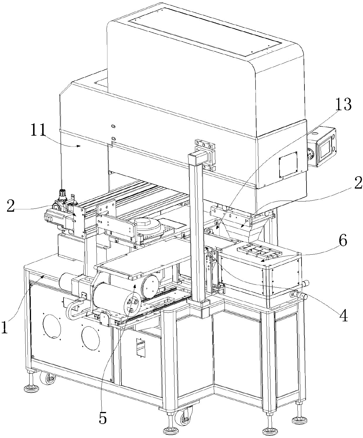
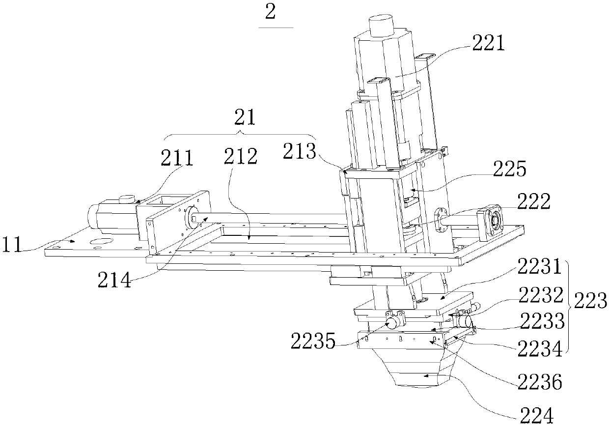
The invention relates to a 3D glass pad printing machine. The 3D glass pad printing machine directly contacts with a marking area of 3D glass and performs ink printing through a mode of glue head padprinting, and comprises a machine frame and a glue head pad printing device, an ink conveying device and a solidifying device which are installed on the machine frame. The glue head pad printing device is used for performing the ink printing on the marking area of the 3D glass. The ink conveying device has a conveying route, and is capable of enabling an ink cup to be moved along the conveying route. The solidifying device is capable of solidifying ink applied on the glue head pad printing device in a heating mode. The invention further provides a method for the 3D glass pad printing. The 3D glass pad printing machine is capable of, through the glue head pad printing device, the ink conveying device, the solidifying device and a cleaning ink-removing device, performing the ink printing onthe 3D glass; performing the gapless combined ink printing on the 3D glass in a sticking mode through using the glue head pad printing device, enabling the ink printed on the 3D glass not to be easilyseparated, improving printing quality, and preventing the ink from being spattered.

Description

technical field [0001] The present invention relates to the technical field of curved glass printing equipment, in particular to a 3D glass pad printing machine, and also to a 3D glass pad printing method based on the 3D glass pad printing machine. Background technique [0002] The characteristics of 3D curved glass meet the design requirements of 3C products. 3C product designs such as smartphones, smart watches, tablet computers, wearable smart products, and dashboards have emerged with 3D products, which have clearly guided the development direction of 3D curved glass. [0003] At present, the manufacturing process of the 3D glass cover window of the mobile phone generally adopts the following three process methods: [0004] 1. The bonding process is to print the decorative pattern on the transparent film first, and then paste it on the inner side of the 3D glass window to complete the processing and production of the 3D glass cover window; [0005] 2. The spraying-expos...

Claims


Application Information

Patent Timeline
Patent Type & Authority Applications(China)
IPC IPC(8): B41F17/00
CPCB41F17/001
Inventor 吴国锋黄泽钙
Owner U P PRECISION AUTOMATED EQUIP CO LTD
Learn More