A multi-purpose mechanized bridge with detachable vehicle and bridge and its erection method

A multi-purpose, vehicle-bridge technology, applied in the direction of construction, etc., can solve the problems of low crossing height, unable to meet the requirements of crossing fire barriers, and affecting the repair time

Active Publication Date: 2020-05-29
CHINA HARZONE IND CORP
View PDF9 Cites 1 Cited by
  • Summary
  • Abstract
  • Description
  • Claims
  • Application Information

AI Technical Summary

Problems solved by technology

Fire barriers have a certain height. When an emergency occurs in the tank farm, repair vehicles cannot quickly cross these barriers, which seriously affects the repair time
The barrier height of existing mechanized bridges is too low to meet the requirements of crossing fire dike barriers

Method used


Image

  • A multi-purpose mechanized bridge with detachable vehicle and bridge and its erection method
  • A multi-purpose mechanized bridge with detachable vehicle and bridge and its erection method
  • A multi-purpose mechanized bridge with detachable vehicle and bridge and its erection method

Examples


Embodiment 1

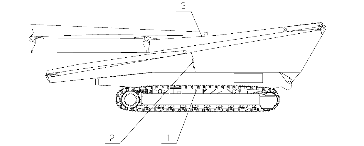
[0020] See attached figure 1 , a multi-purpose mechanized bridge with detachable axles, which includes: a crawler chassis vehicle 1, a connecting bridge 2 and a detachable bridge 3;

[0021] The crawler chassis vehicle 1 includes: a vehicle body 4 and a walking system 5 and a power drive system 6 installed under the vehicle body 4;

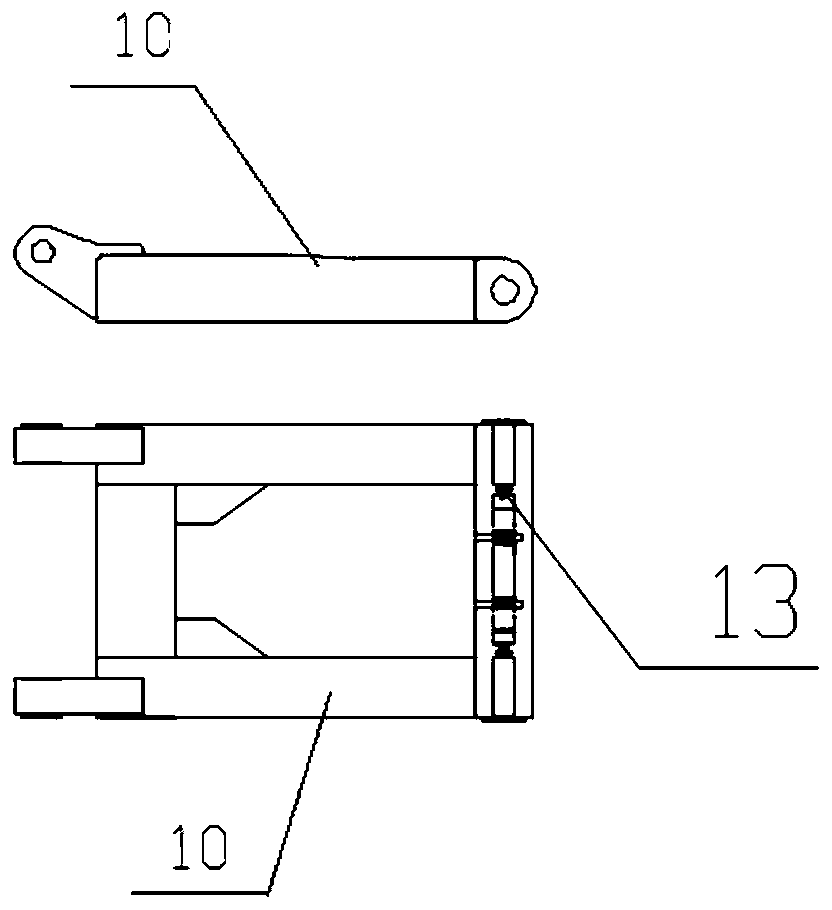
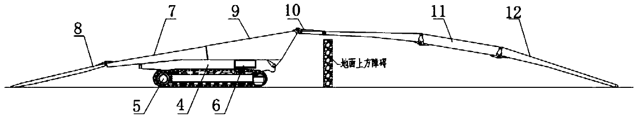
[0022] See attached Figure 2-3 , the connecting bridge 2 includes: a fixed bridge body 7, a rear springboard 8, an overturned bridge body 9, a connecting bridge mechanism 10, and a lateral telescopic mechanism 13; One end of the springboard 8 is hinged with the tail of the fixed bridge body 7, and can be turned around the joint point under the drive of external force, so that the tail springboard 8 can be stacked on the top of the fixed bridge body 7; The lugs are hinged to the car body 4, and the flip bridge body 9 can be turned around the hinge point under the drive of external force. When not turned over, the flip bridge body 9 is stacked on...

Embodiment 2

[0027] A method for erecting a detachable multi-purpose mechanized bridge, based on the detachable multi-purpose mechanized bridge as described in Embodiment 1, its technical scheme is:

[0028] In transport state: both the connecting bridge 2 and the detachable bridge 3 are folded, such as figure 1 As shown, at this time, the tail springboard 8 in the connecting bridge 2 is folded on the upper end surface of the fixed bridge body 7, the tail end surface of the inverted bridge body 9 is fitted with the head end surface of the fixed bridge body 7, and the connecting bridge mechanism 10 is folded on the flipped surface. The upper end surface of the bridge body 9; the detachable bridge 3 is folded above the connecting bridge 2, wherein the tail bridge section 12 is flipped and folded above the middle bridge section 11.

[0029] See attached image 3 , when the vehicle and bridge are erected in one piece, the connecting bridge mechanism 10 in the connecting bridge 2 is connected ...


PUM


Abstract

The invention relates to the technical field of mechanized bridges, in particular to a mechanized bridge separable from a vehicle bridge and a method for erecting the same. The utility model relates to a detachable multi-purpose mechanized bridge, comprising a tracked chassis car, a connecting bridge and a detachable bridge; The connecting bridge comprises a fixed bridge body, a tail springboard,a turnover bridge body, a connecting bridge mechanism and a transverse expansion and contraction mechanism; Separable bridges include: head bridge section, middle bridge section and tail bridge section; The invention not only can be used as a bridge vehicle, but also can be used as a bridge vehicle separately. When an emergency occurs in the tank farm of the oil depot, the invention can quickly erect a bridge passage across the fire dike of the oil depot by integrating a vehicle and a bridge, so as to realize crossing the obstacle above the ground; At that same time, the vehicle-bridge separation erection method can also be use for erecting the vehicle-bridge separation erection, and the temporary fast bridge can be built to cross the obstacle such as rivers and gullies, and the like, andthe support function can be realized.

Description

technical field [0001] The invention relates to the technical field of mechanized bridges, in particular to a mechanized bridge with detachable vehicle axles. Background technique [0002] In the petrochemical industry oil storage depot area, considering the requirements of fire protection, a fully enclosed fire dike is installed around the outside of each oil storage tank area, and there is no passage for vehicles and other equipment to directly enter the tank area. The fire barriers have a certain height. When an emergency occurs in the tank farm, the repair vehicles cannot quickly cross these barriers, which seriously affects the repair time. Existing mechanized bridges have low barrier heights and cannot meet the requirements for crossing fire barriers. Contents of the invention [0003] The purpose of the present invention is to provide a multi-purpose mechanized bridge that can quickly erect a bridge passage across the fire embankment of the oil depot when an emerge...

Claims


Application Information

Patent Timeline
Patent Type & Authority Patents(China)
IPC IPC(8): E01D15/127
CPCE01D15/127
Inventor 王瑞吴茂许冉陆凯方俊刘加顺张涛王亚国余力
Owner CHINA HARZONE IND CORP
Why Eureka
Try Eureka