Multi-parameter collaborative test method for electromagnetic radiation of rail vehicle

A technology of electromagnetic radiation and testing methods, which is applied in the direction of railway vehicle testing, electromagnetic field characteristics, measuring devices, etc., can solve the problems that cannot be provided in real time, and achieve the effects of easy diagnosis, accurate test results, and simple and efficient testing methods

Active Publication Date: 2018-12-21
CRRC CHANGCHUN RAILWAY VEHICLES CO LTD +1
View PDF9 Cites 1 Cited by
  • Summary
  • Abstract
  • Description
  • Claims
  • Application Information

AI Technical Summary

Problems solved by technology

[0005] In order to solve the technical problems that the existing dynamic test method cannot provide the speed value, acceleration value and distance value relative to the test starting position of each carriage in real time, resulting in the inability to realize the test of a single carriage and inaccurate test results, The invention provides a multi-parameter collaborative testing method for rail vehicle electromagnetic radiation, which provides an effective method for separately testing each carriage in the rail vehicle electromagnetic radiation dynamic test, and facilitates on-site diagnosis of the problem that the electromagnetic radiation value of the whole vehicle exceeds the standard, and realizes It improves the automatic sampling of vehicle speed parameters and compartment position information, as well as the intelligent display of test operation information, and improves the efficiency and test accuracy of electromagnetic radiation type tests for rail vehicles

Method used


Image

  • Multi-parameter collaborative test method for electromagnetic radiation of rail vehicle
  • Multi-parameter collaborative test method for electromagnetic radiation of rail vehicle
  • Multi-parameter collaborative test method for electromagnetic radiation of rail vehicle

Examples


Embodiment Construction

[0025] The present invention will be further described in detail below in conjunction with the drawings and embodiments.

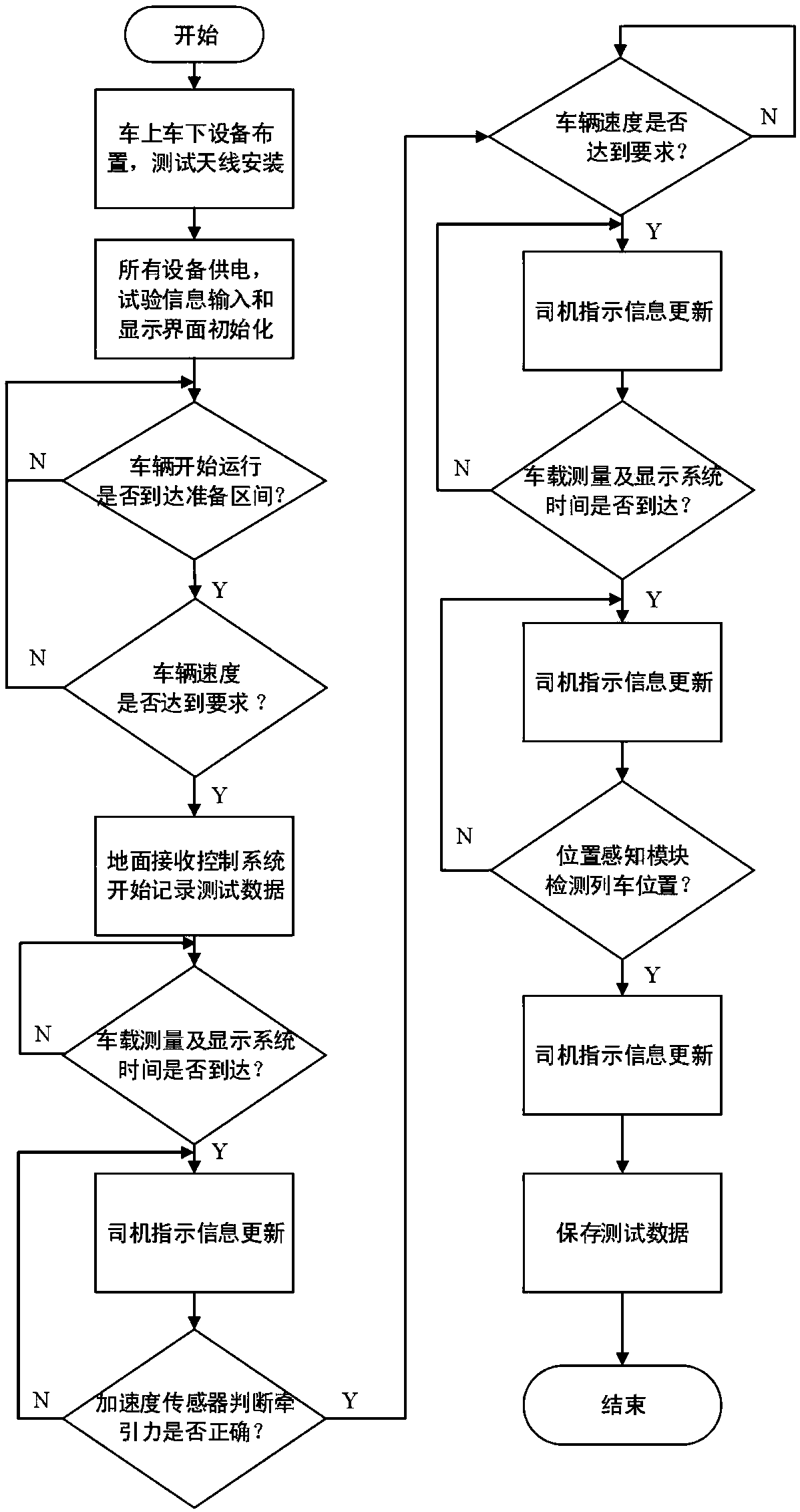
[0026] The multi-parameter coordinated test method for electromagnetic radiation of rail vehicles of the present invention includes the following steps:

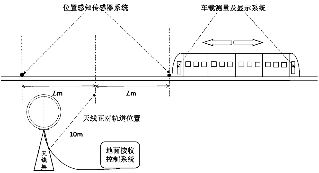
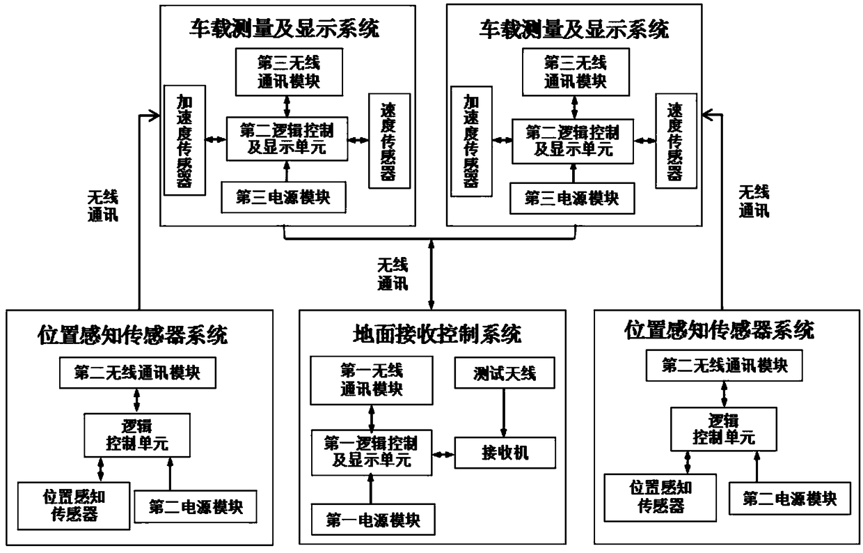
[0027] Step 1: Such as Figure 1 to Figure 3 As shown, a set of ground receiving control system is selected on the ground next to the track to select a section of a flat track, including a test antenna used to measure electromagnetic radiation, a receiver, a first logic control and display unit, a first wireless communication module and a second A power supply module; a set of position sensing sensor systems are symmetrically arranged at a position L on both sides of the above-mentioned test antenna. The position sensing sensor system includes a second power supply module, a position sensing sensor, a second wireless communication module and a logic control unit; A set of on-board measurement and display sys...


PUM


Abstract

The invention discloses a multi-parameter collaborative test method for electromagnetic radiation of a rail vehicle, and relates to the technical field of rail transit electromagnetic compatibility tests. According to the method, a straight rail section is selected for arrangement of a set of ground receiving control system, two sets of position sensing sensor systems are symmetrically arranged atpositions with a distance of L to two sides of a test antenna, a set of on-board measurement and display system is arranged in each of driver's cabs of heads at both ends of the rail vehicle; the on-board measurement and display systems obtain speed and acceleration of the rail vehicle in real time to achieve real-time communication between measured data and the ground receiving control system, and a display interface guides a driver to operate; the position sensing sensor systems provide position information of the rail vehicle, sense a position where the head arrives, and inform the on-board measurement and display systems of the position information through a wireless communication unit; the ground receiving control system realizes test flow setting and measurement and data storage anddisplay of the electromagnetic radiation of the vehicle. The method realizes dynamic tests of each compartment, and facilitates diagnosis of the problem of excessive electromagnetic radiation.

Description

Technical field [0001] The invention relates to the technical field of rail transit electromagnetic compatibility testing, in particular to a method for multi-parameter coordinated testing of rail vehicle electromagnetic radiation. Background technique [0002] Modern rail vehicles integrate huge and complex electrical, communication and signal systems. The electromagnetic radiation generated by the vehicles is an important test item for product type tests. According to the relevant standards for electromagnetic compatibility of rail vehicles, static and dynamic electromagnetic radiation tests on the vehicles are required in the electromagnetic radiation test to determine whether the maximum electromagnetic radiation generated by the train meets the standard requirements. The static electromagnetic radiation test is carried out under the condition that each carriage and the test antenna are stationary. The position is adjusted and the test is easier to carry out. The dynamic ope...

Claims


Application Information

Patent Timeline
Patent Type & Authority Applications(China)
IPC IPC(8): G01R29/08G01M17/08
CPCG01M17/08G01R29/0821G01R29/0835G01R29/0871
Inventor 赵塔刘雪明李鸷
Owner CRRC CHANGCHUN RAILWAY VEHICLES CO LTD
Why Eureka
Try Eureka