Displacement sensor structure and testing method
A technology of displacement sensor and testing method, applied in the direction of instruments, measuring devices, mechanical measuring devices, etc., can solve the problems of high price, fast impact speed, large measurement error, etc., to achieve convenient installation and use, solve measurement errors, and eliminate installation errors. Effect
- Summary
- Abstract
- Description
- Claims
- Application Information
AI Technical Summary
Problems solved by technology
Method used
Image

Examples
Embodiment 1
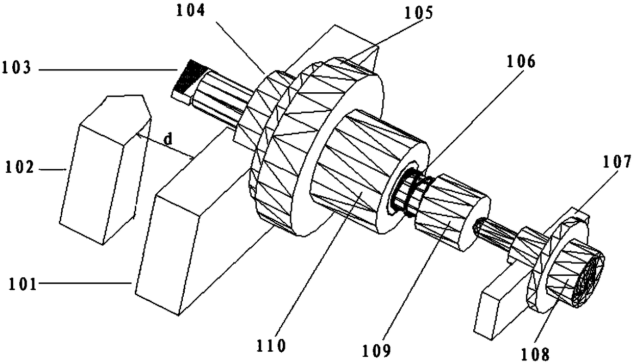
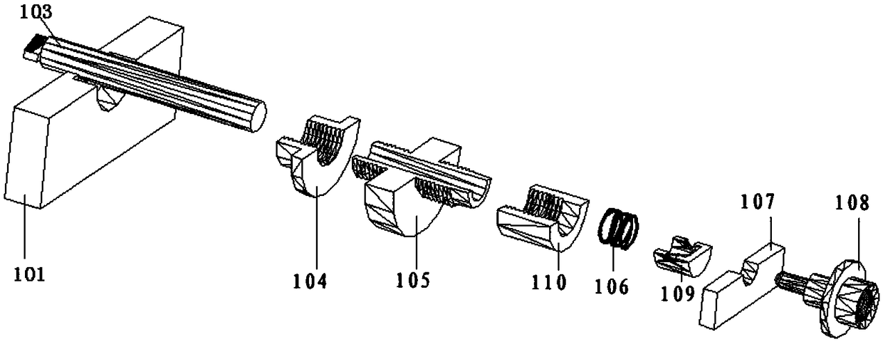
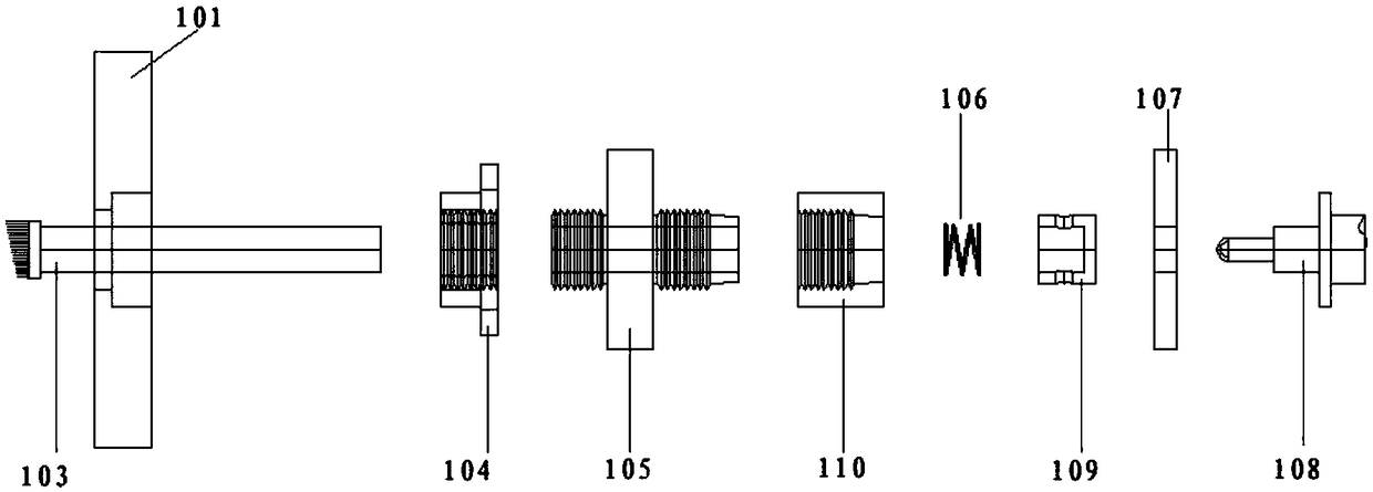
[0028] see Figure 1-3 , the present embodiment provides a displacement sensor structure, including:
[0029] A displacement sensor 103 composed of a head and a circular shaft. The head is in an asymmetrical structural shape and placed between the fixed part 101 and the moving part 102. The circular shaft is fixed on the fixed part through the mounting seat 104, and Pass through the measuring nozzle 105 installed in the installation seat 104 at one end, and lock it with a locking headgear 109;
[0030] The locking ring 110 is used in conjunction with the other end of the measuring mouth 105, and is used to lock the circular shaft of the displacement sensor 103;
[0031] The spring 106 placed between the measuring mouth 105 and the locking headgear 109 is used to apply a force away from the moving part 102 to the circular axis of the sensor, so that the displacement sensor 103 can be reset;
[0032] The screw micrometer mechanism applies a thrust to the arithmetic subtraction...
Embodiment 2
[0045] This embodiment provides a testing method for a displacement sensor structure, including the following steps:
[0046] S101, the locking ring 110 does not lock the displacement sensor 103 first, so that the rotating screw micrometer mechanism 108 can control the head of the transmission displacement sensor 103 to move axially along the circular axis;
[0047] S102, use the calibration block as a zero point reference, so that the head of the displacement sensor 103 does not expose the fixed part, record the position displayed by the screw micrometer mechanism 108 at this time, and record it as the zero point position L1 of the gap;
[0048] S103, remove the calibration block, control the screw micrometer mechanism 108 to move the head of the displacement sensor 103 until the moving part can cut the head, record the position displayed by the screw micrometer mechanism 108 at this time, and record it as position L2 , then the cold state gap is L2-L1, and record the initial...
PUM
 Abstract
Description
Claims
Application Information
 - R&D
- Intellectual Property
- Life Sciences
- Materials
- Tech Scout
- Unparalleled Data Quality
- Higher Quality Content
- 60% Fewer Hallucinations
Browse by: Latest US Patents, China's latest patents, Technical Efficacy Thesaurus, Application Domain, Technology Topic, Popular Technical Reports.
© 2025 PatSnap. All rights reserved.Legal|Privacy policy|Modern Slavery Act Transparency Statement|Sitemap|About US| Contact US: help@patsnap.com