
Three-dimensional Displacement Measurement Sensor Based on Polymer Optical Fiber

A displacement measurement and sensor technology, applied in the direction of measuring devices, instruments, optical devices, etc., can solve the problems of low precision, multi-dimensional displacement sensors susceptible to interference, high cost, etc., and achieve wide measurement range, good sensitivity and accuracy, and low cost low effect

Active Publication Date: 2020-05-22
ZHONGBEI UNIV
View PDF6 Cites 0 Cited by
  • Summary
  • Abstract
  • Description
  • Claims
  • Application Information

AI Technical Summary

Problems solved by technology

[0008] In order to solve the problem that the existing multi-dimensional displacement sensor is either susceptible to interference, or has low precision or high cost, the present invention provides a three-dimensional displacement measurement sensor based on polymer optical fiber

Method used


Image

  • Three-dimensional Displacement Measurement Sensor Based on Polymer Optical Fiber
  • Three-dimensional Displacement Measurement Sensor Based on Polymer Optical Fiber
  • Three-dimensional Displacement Measurement Sensor Based on Polymer Optical Fiber

Examples


Embodiment Construction

[0027] The present invention will be further described below in conjunction with specific examples.

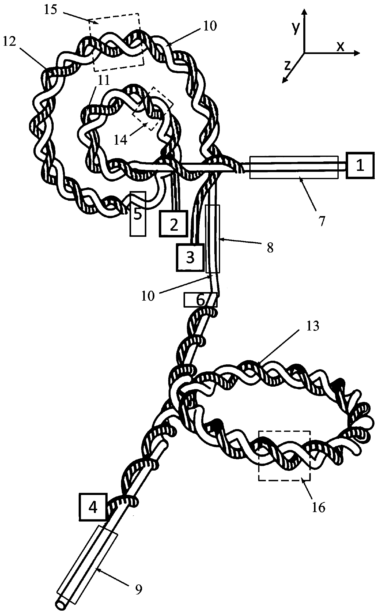
[0028] A three-dimensional displacement measurement sensor based on polymer optical fiber, such as figure 1 Shown: including X axis, Y axis and Z axis, first passive optical fiber 11, second passive optical fiber 12, third passive optical fiber 13 and active optical fiber 10, said first passive optical fiber 11, second The passive optical fiber 12 and the third passive optical fiber 13 are all twisted paired with the active optical fiber 10. After one end of the active optical fiber 10 is connected to the LED light source 1, it is first twisted paired with the first passive optical fiber 11 to form a first pair Twisted fiber 14, the initial section of the first twisted-pair fiber 14 is fixed on the X-axis moving plate 7, and the remaining part is bent to form a circular shape to form a first macrobend coupling structure, and the first macrobend coupling structure is located at...


PUM


Abstract

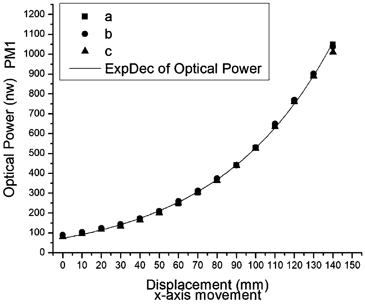
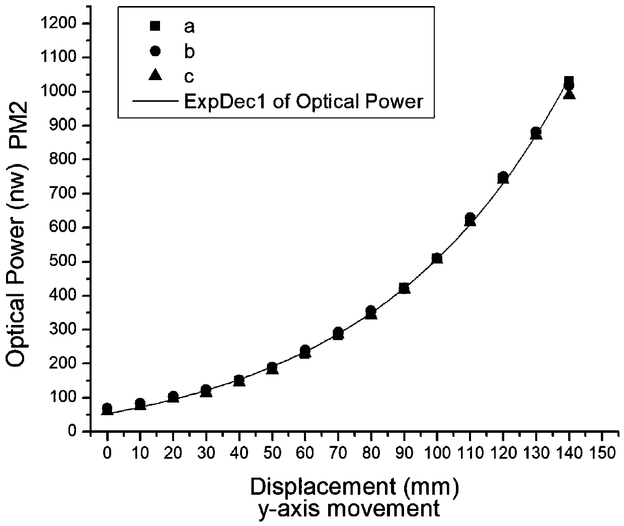
The invention discloses a three-dimensional displacement measuring sensor based on a polymer optical fiber, and is used for measuring displacements in three directions. The three-dimensional displacement measuring sensor comprises an X-axis direction, a Y-axis direction and a Z-axis direction, and each direction corresponds to a passive optical fiber. The passive optical fibers in the three directions are both twisted with the active optical fibers to form twisted fibers, and respective one section of each of the twisted fibers in three directions are fixed to the X-axis direction moving plate, the Y-axis direction moving plate and the Z-axis direction moving plate respectively, and the remaining parts are bent into a circle to form three macrobend coupling structures respectively. The macrobend coupling structure can couple the light in the active fiber into each passive fiber, so that the optical power meter corresponding to the end of the passive fibers can detect the light intensity. The increase in displacement of the moving plates in three directions reduces the bend radius of each macrobend coupling structure, so that the active optical fibers can couple more light to the passive optical fibers, the three optical power meters can detect the changes of light intensity, and the changes of displacement in three directions can be measured by converting the light intensity into a displacement.

Description

technical field [0001] The invention relates to the application field of optical fiber macro-bending coupling, in particular to a multi-dimensional displacement measurement sensor based on polymer optical fiber, which is suitable for detecting displacement in three-dimensional directions in industry. Background technique [0002] There are some obvious problems in industrial applications that require the use of directional displacement sensors to measure displacement in two, three or more dimensions. Traditional displacement sensors are magnetic induction, photoelectric, potentiometer, transformer, Hall type, winding, capacitive type, etc. These traditional displacement sensors are relatively mature technologies and are deployed in different industrial applications. However, in addition to some advantages, the traditional method also has many disadvantages, and the compatible technology of this traditional technology is the fiber-based system. These fiber optic sensors hav...

Claims


Application Information

Patent Timeline
Patent Type & Authority Patents(China)
IPC IPC(8): G01B11/02
CPCG01B11/02
Inventor 刘文怡阿卜杜勒·加法尔侯钰龙高琬佳张会新萨达姆·侯赛因穆贾希德梅迪
Owner ZHONGBEI UNIV
Learn More