
An optical waveguide group refractive index testing device and method

A group refractive index and testing device technology, which is applied in measuring devices, optical instrument testing, and refractive power measurement, can solve problems such as difficult group refractive index Ng testing, large group refractive index errors, and large testing errors, so as to improve testing The effect of flexibility, reducing test error and improving test accuracy

Active Publication Date: 2021-07-27
ZHONGXING PHOTONICS TECH CO LTD
View PDF9 Cites 0 Cited by
  • Summary
  • Abstract
  • Description
  • Claims
  • Application Information

AI Technical Summary

Problems solved by technology

However, both of them have problems such as large test error or narrow test range, because the error in finding the resonance wavelength λ and the free spectral range (FSR: Freespectrum range) according to the spectrum is relatively large, so the error of the measured group refractive index is relatively large. Big
And for other optical waveguides (such as: ridge waveguide: Rib waveguide) or other devices other than the simplest strip optical waveguide, the traditional test method has the problem of large test error or difficult to test the group refractive index Ng

Method used


Image

  • An optical waveguide group refractive index testing device and method
  • An optical waveguide group refractive index testing device and method
  • An optical waveguide group refractive index testing device and method

Examples


Embodiment 1

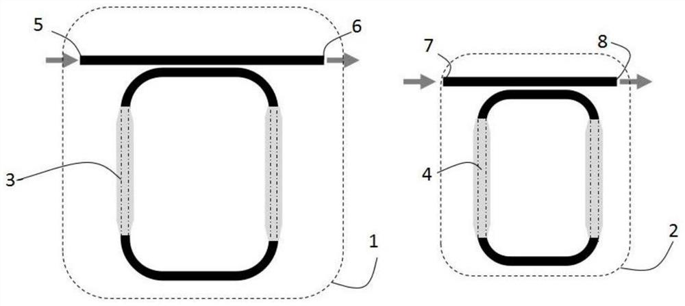
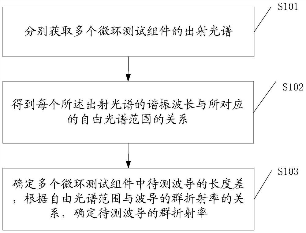
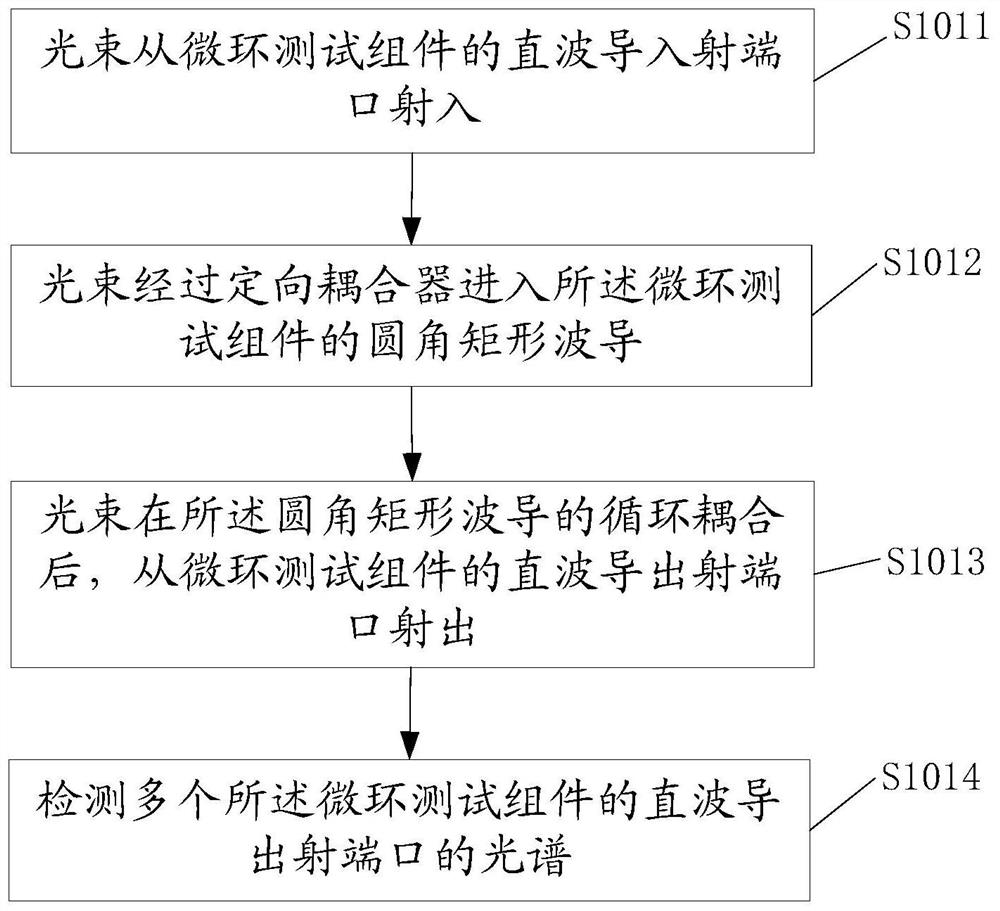
[0085] like figure 1 As shown in the figure, the light beams are respectively injected from the direct wave guide entrance port 5 of the first micro-ring test assembly 1 and the direct wave guide entrance port 7 of the second micro-ring test assembly 2, and are coupled into the micro-ring test assembly through the directional coupler. After the sub-cycle coupling, it is emitted from the straight-wave exit port 6 of the first micro-ring test assembly 1 and the direct-wave exit port 8 of the second micro-ring test assembly 2; respectively, the test spectra of the two micro-ring test assemblies are obtained, and from the spectra get the resonant wavelength λ 1 and its corresponding FSR 1 (λ) relationship and resonant wavelength λ 2 and its corresponding FSR 2 (λ) relationship: FSR∝λ. Finally, the group refractive indices Ng of the first waveguide 3 to be tested and the second waveguide 4 to be tested are calculated and obtained.

[0086] In this embodiment, a fully etched st...

Embodiment 2

[0089] like figure 1 As shown in the figure, the light beams are respectively injected from the direct wave guide entrance port 5 of the first micro-ring test assembly 1 and the direct wave guide entrance port 7 of the second micro-ring test assembly 2, and are coupled into the micro-ring test assembly through the directional coupler. After the sub-cycle coupling, it is emitted from the straight-wave exit port 6 of the first micro-ring test assembly 1 and the direct-wave exit port 8 of the second micro-ring test assembly 2; respectively, the test spectra of the two micro-ring test assemblies are obtained, and from the spectra get the resonant wavelength λ 1 and its corresponding FSR 1 (λ) relationship and resonant wavelength λ 2 and its corresponding FSR 2 (λ) relationship: FSR∝λ. Finally, the group refractive indices Ng of the first waveguide 3 to be tested and the second waveguide 4 to be tested are calculated and obtained.

[0090]In this embodiment, a shallow etched r...


PUM

PropertyMeasurementUnit
transmittivityaaaaaaaaaa

Abstract

The present application proposes a device and method for testing the refractive index of an optical waveguide group. The device includes: a plurality of microring test components, each of which includes a straight waveguide and a rounded rectangular waveguide, and the rounded rectangular waveguide Parallel to the straight waveguide and close to one side of the straight waveguide to form a directional coupler with the straight waveguide, the rounded rectangular waveguide is perpendicular to at least one side of the straight waveguide to set the waveguide to be tested, and the plurality of microrings The waveguides to be tested in the test components have different lengths, and the multiple microring test components are the same except for the waveguides to be tested in different lengths. The invention has the advantages of high testing precision, wide measurable range and the like.

Description

technical field [0001] The invention relates to the technical field of optical waveguide group refractive index (Ng: Group index) testing, in particular to an optical waveguide group refractive index testing device and method. Background technique [0002] In recent years, in order to meet people's growing needs for communication and vast data transmission, optical communication technology has developed rapidly; among them, the performance of silicon optical devices has become increasingly sophisticated, and silicon-based photonic integrated chips are characterized by low cost, high transmission speed and high integration. It has received great attention from people and has become one of the trendsetters of the next generation of information revolution. As the most basic structure in silicon-based photonic integrated chips, the performance of optical waveguides plays a decisive role. At present, the design principle of many devices is based on the group refractive index of ...

Claims


Application Information

Patent Timeline
Patent Type & Authority Patents(China)
IPC IPC(8): G01M11/00G01M11/02
CPCG01M11/0228G01M11/335
Inventor 顾凯吉勇宁沈百林
Owner ZHONGXING PHOTONICS TECH CO LTD
Learn More