
Hydraulic lifting platform for wind and solar generator test

A technology of hydraulic lifting and generator, applied in the field of hydraulic lifting platform, can solve the problems of not being able to understand the changes of the light angle and wind speed of the generator in time, not being able to repair and disassemble quickly, affecting the detection of test objects, etc. Power generation, the effect for easy comparison

Active Publication Date: 2018-12-28
芜湖双港特色旅游有限公司
View PDF12 Cites 0 Cited by
  • Summary
  • Abstract
  • Description
  • Claims
  • Application Information

AI Technical Summary

Problems solved by technology

[0002] The hydraulic lifting platform is a workbench that is driven up and down by the hydraulic rod and the electric motor. However, with the development of science and technology, people's requirements for the hydraulic lifting platform are getting higher and higher. As a result, the traditional hydraulic lifting platform can no longer meet people's needs. People need a hydraulic lifting platform that can more conveniently replace the experimental object and repair the motor; the existing hydraulic lifting platform has certain disadvantages in use, first of all, the existing hydraulic lifting platform for experiments cannot be used in a good Fixing and fast replacement at the same time, so that the replacement needs to waste a lot of time, which affects the detection of the test object. Secondly, the hydraulic lifting platform for the experiment needs the continuous and efficient work of the motor. The motor is prone to damage and cannot be repaired and disassembled quickly, which affects the use. , finally, it is impossible to know the changes of the illumination angle and wind speed at the location of the generator in time, which makes the detection of the generator have certain limitations and has a certain impact on people's use process. Therefore, we propose a method for Hydraulic lifting table for wind and solar generator test

Method used


Image

  • Hydraulic lifting platform for wind and solar generator test
  • Hydraulic lifting platform for wind and solar generator test
  • Hydraulic lifting platform for wind and solar generator test

Examples


Embodiment Construction

[0018] In order to make the technical means, creative features, objectives and effects of the present invention easy to understand, the present invention will be further explained below in conjunction with specific embodiments.

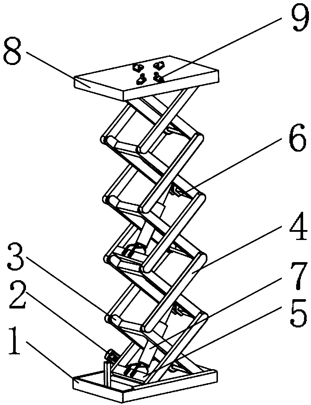
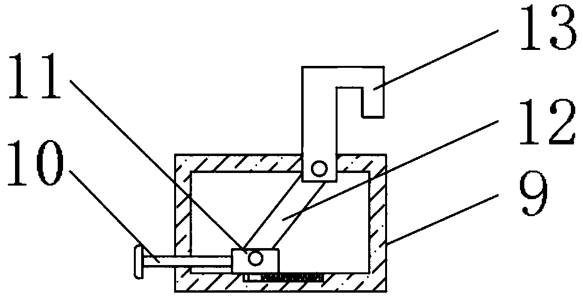
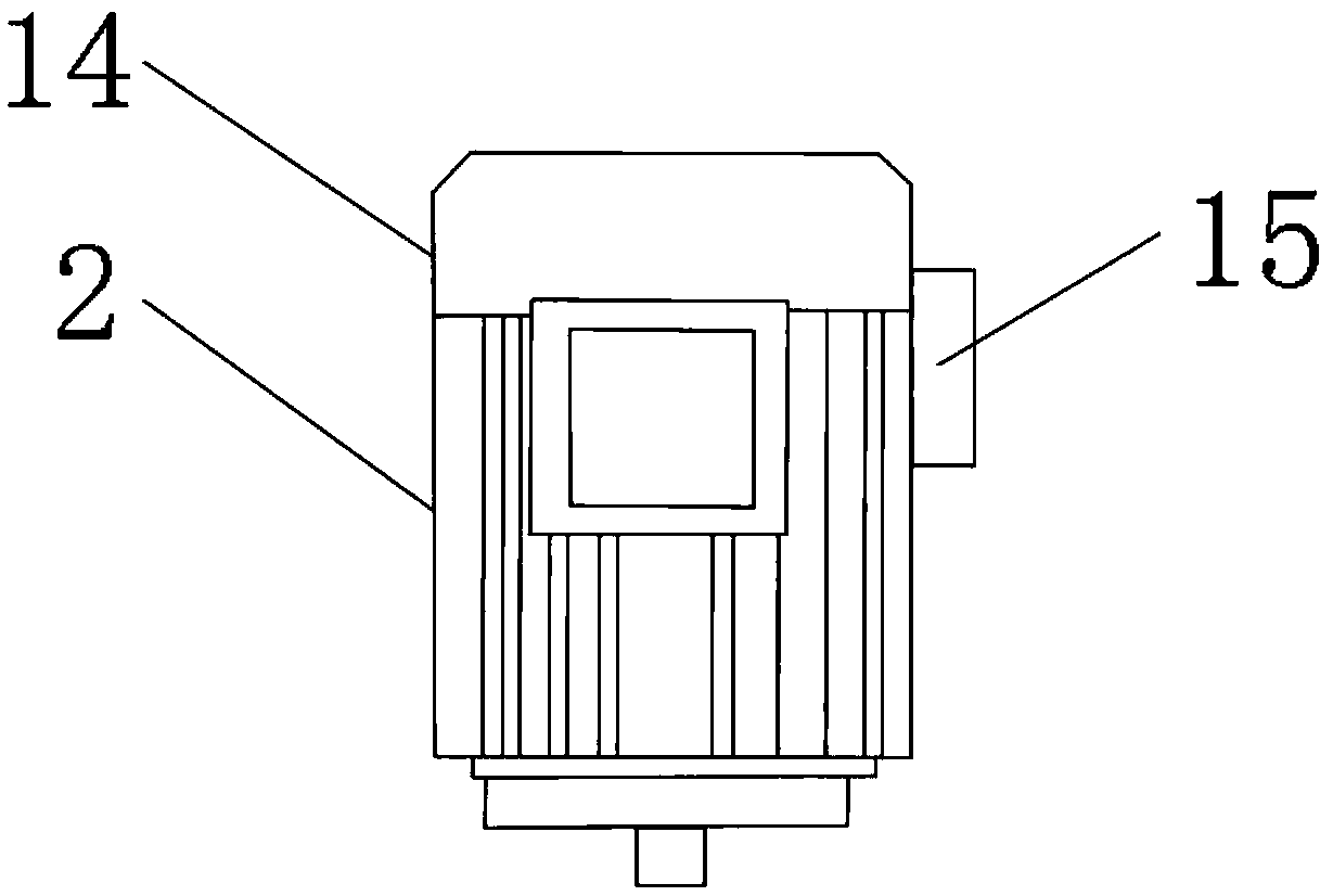
[0019] Such as Figure 1-5 As shown, a hydraulic lifting platform for wind and solar generator tests includes a hydraulic main body 1, one side of the outer surface of the hydraulic main body 1 is provided with an electric motor 2, and the top outer surface of the hydraulic main body 1 is movably installed with a pole 3 With the second pole 4, and the second pole 4 is located on one side of the first pole 3, the outer surface of the first pole 3 is close to the bottom end, and a fixed plate 5 is fixedly installed, and the outer surface of the first pole 3 is close to The No. 2 fixing plate 6 is fixedly installed at the top position, and a hydraulic rod 7 is arranged between the No. 1 fixing plate 5 and the No. 2 fixing plate 6. A placement plate 8 is pro...


PUM


Abstract

The invention discloses a hydraulic lifting platform for a wind and solar generator test, which comprises a hydraulic body. An electric motor is provided on an outer surface of one side of the hydraulic body. The outer surface of a top end of the hydraulic body is movably provided with a first rod and a second rod, and the second rod is located on one side of the first rod. A first fixed plate isfixedly mounted on the outer surface, near the bottom end, of one side of the first rod. The hydraulic lifting platform for a wind and solar generator test of the invention is provided with a fixed frame, a buckle, a sensitive plate and a light shielding rod, which can better fix different generators, and it is more convenient to quickly replace different generators to avoid affecting the detection progress. The electric motor can be quickly repaired to avoid affecting the timely use of the electric motor. The illumination angle can also be well detected, and generator operation under different illumination angles can be detected, which leads to better use prospects.

Description

Technical field [0001] The invention relates to the field of hydraulic lifting platforms, in particular to a hydraulic lifting platform used for wind and solar generator tests. Background technique [0002] A hydraulic lifting platform is a work platform that is lifted and lowered by a hydraulic rod and an electric motor. However, with the development of science and technology, people’s requirements for hydraulic lifting platforms are getting higher and higher, which has caused traditional hydraulic lifting platforms to no longer satisfy people’s use. Demand, people need a hydraulic lifting platform that can more easily replace the experimental objects and facilitate the repair of the motor; the existing hydraulic lifting platform has certain drawbacks when in use. First of all, the existing experimental hydraulic lifting platform cannot perform well. It is fixed and quick replacement is realized at the same time, so that a lot of time is wasted for replacement, which affects the...

Claims


Application Information

Patent Timeline
IPC IPC(8): G01R31/34G01R1/04
CPCG01R1/04G01R31/34
Inventor 马振博李安政
Owner 芜湖双港特色旅游有限公司
Features
  • Generate Ideas
  • Intellectual Property
  • Life Sciences
  • Materials
  • Tech Scout
  • Unparalleled Data Quality
  • Higher Quality Content
  • 60% Fewer Hallucinations
Learn More