
Driving circuit board and display device

A technology for driving circuit boards and display devices, applied in circuits, measuring devices, measuring electronics, etc., can solve problems such as easy damage to test circuits, and achieve the effects of avoiding adverse effects, avoiding breakdown, and avoiding static electricity accumulation

Pending Publication Date: 2018-12-28
KUNSHAN GO VISIONOX OPTO ELECTRONICS CO LTD
View PDF5 Cites 1 Cited by
  • Summary
  • Abstract
  • Description
  • Claims
  • Application Information

AI Technical Summary

Problems solved by technology

[0004] Based on this, it is necessary to provide a driving circuit board and a display device for the problem that the test circuit of the circuit board is easily damaged.

Method used


Image

  • Driving circuit board and display device
  • Driving circuit board and display device
  • Driving circuit board and display device

Examples


Embodiment Construction

[0036] In order to make the purpose, technical solution and technical effect of the present invention clearer, specific embodiments of the present invention will be described below in conjunction with the accompanying drawings. It should be understood that the specific embodiments described here are only used to explain the present invention, not to limit the present invention.

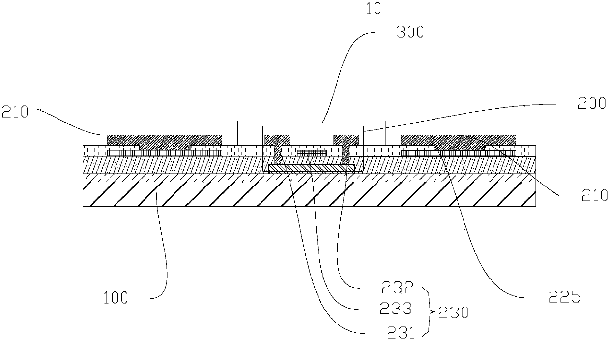
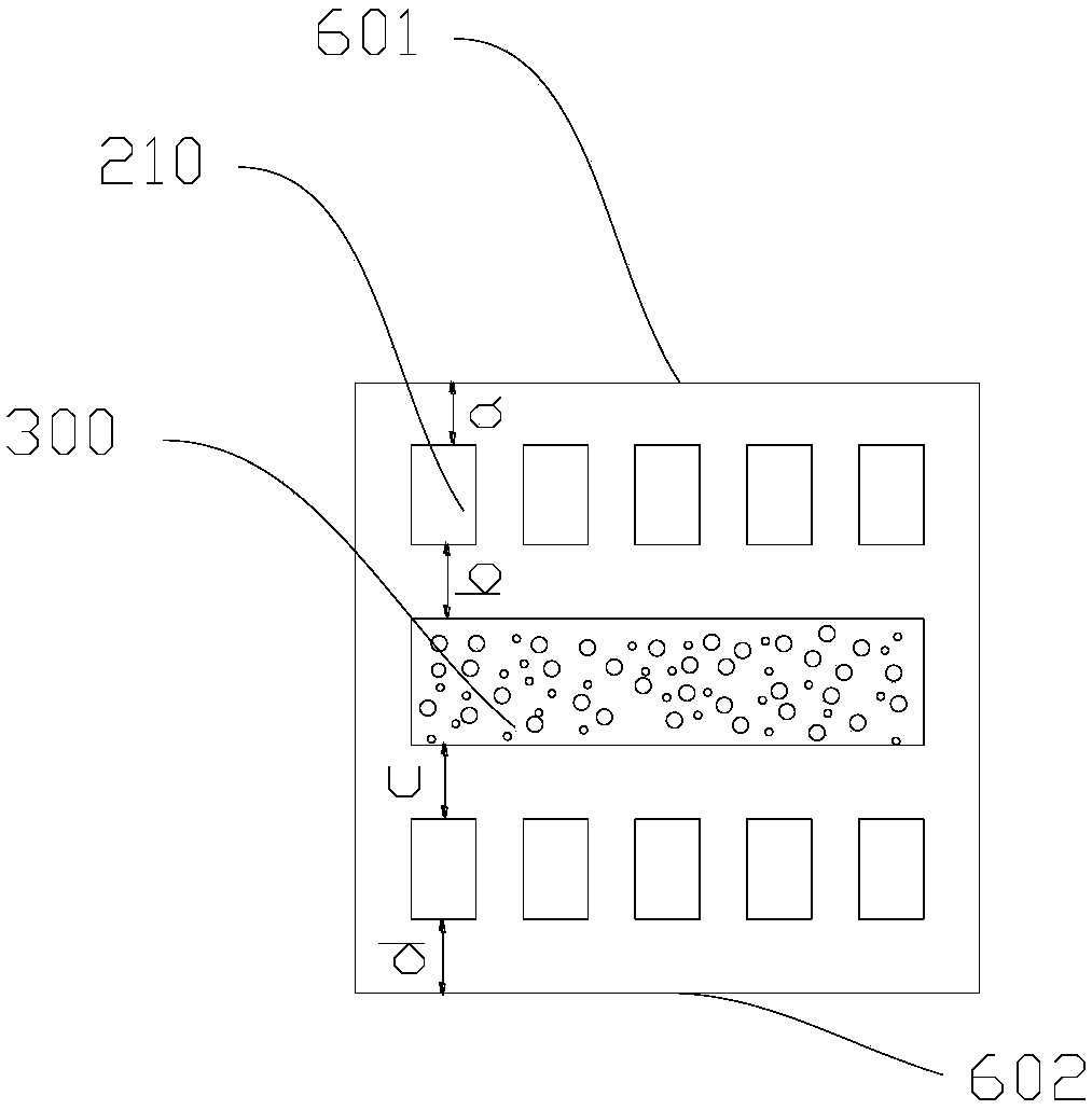
[0037] See figure 1 , the present invention provides a driving circuit board 10 . The driving circuit board 10 includes a substrate 100 , a test circuit 200 disposed on the substrate 100 , and a protective layer 300 disposed on the surface of the test circuit 200 . The substrate includes a display area 500 and a non-display area 600 , and the test circuit 200 is disposed in the non-display area 600 .

[0038] The substrate 100 can be a glass substrate, a flexible plastic substrate, or a substrate made of other organic materials with certain strength.

[0039] In one embodiment, the driving circuit ...


PUM


Abstract

The invention discloses a driving circuit board and a display device. The driving circuit board comprises a substrate, and a test circuit and two connection units which are arranged on the surface ofthe substrate, wherein the two connection units are arranged at two sides of the test circuit, and a protection layer arranged on the surface of the test circuit is further included. The driving circuit board is advantaged in that lines of the test circuit can be prevented from being corroded or damaged through the protection layer.

Description

technical field [0001] The invention relates to the display field, in particular to a driving circuit board and a display device. Background technique [0002] An installation circuit is arranged on the non-display area of ​​the substrate of the screen body of the display device. The mounting circuit usually includes input pads and output pads disposed opposite to each other, with an exposed test circuit between the input pads and the output pads. The input pins and output pins of the integrated circuit chip are respectively connected to the input pads and the output pads, so that the integrated circuit chip is electrically connected to the substrate. [0003] In the prior art, the test circuit is easily damaged, especially easily broken down by static electricity. After the test circuit is damaged, it will lead to wrongly judge whether the screen body is good or not. This is very unfavorable for the production of the screen body. Contents of the invention [0004] Bas...

Claims


Application Information

Patent Timeline
IPC IPC(8): G09G3/32G09G3/00
CPCG09G3/006G09G3/32H01L29/786G09G3/00H10K71/70H10K59/131G01R31/2825H01L22/34H01L23/60H01L27/1244H01L27/1262
Inventor 张金方张露韩珍珍胡思明王向前刘青刚朱晖
Owner KUNSHAN GO VISIONOX OPTO ELECTRONICS CO LTD
Learn More