Display module and display device

A display module and display area technology, applied in the direction of instruments, circuits, electric solid devices, etc., can solve the problems of polarizer failure, static electricity accumulation, etc., and achieve the effect of avoiding static electricity accumulation

Pending Publication Date: 2021-04-30
WUHAN TIANMA MICRO ELECTRONICS CO LTD
View PDF0 Cites 4 Cited by
  • Summary
  • Abstract
  • Description
  • Claims
  • Application Information

AI Technical Summary

Problems solved by technology

[0003] This application provides a display module and a display device, aiming to solve the problem

Method used


Image

  • Display module and display device
  • Display module and display device
  • Display module and display device

Examples


Embodiment Construction

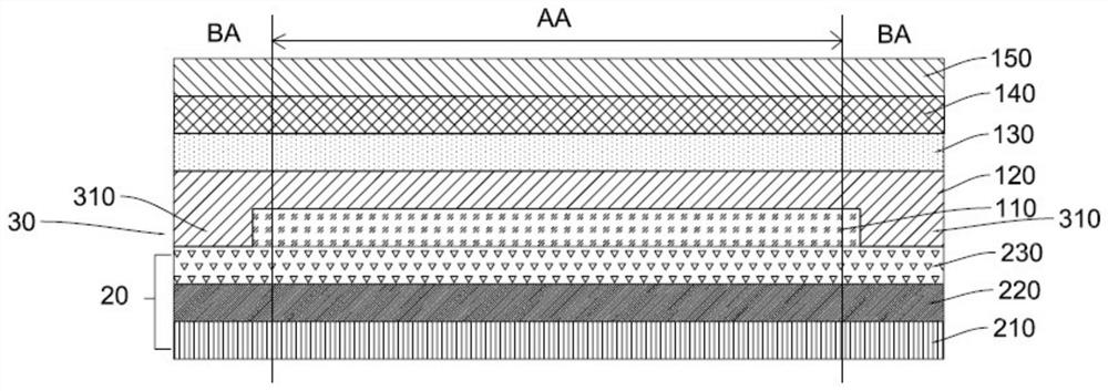
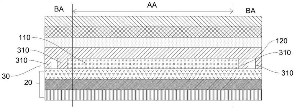
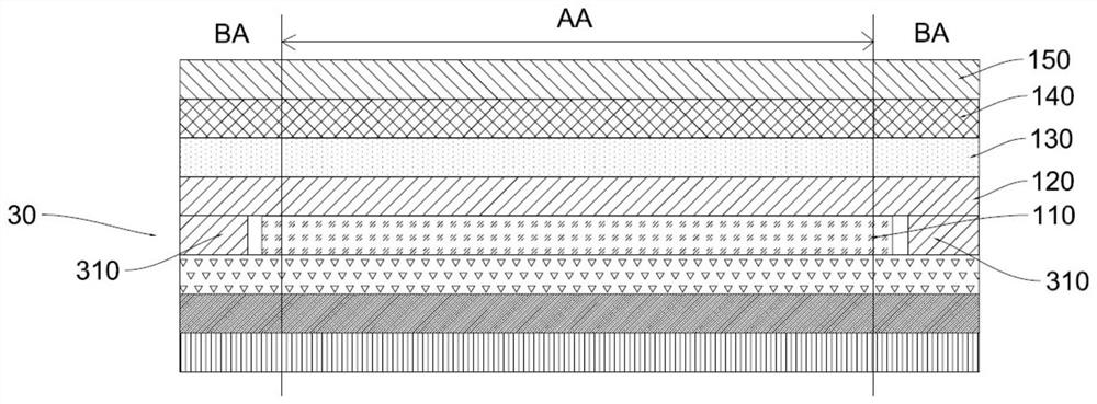
[0023] The implementation manner of the present application will be further described in detail below with reference to the drawings and embodiments. The detailed description and drawings of the following embodiments are used to illustrate the principles of the application, but not to limit the scope of the application, that is, the application is not limited to the described embodiments.

[0024] In the description of this application, it should be noted that, unless otherwise specified, the meaning of "plurality" is more than two; the terms "upper", "lower", "left", "right", "inner", " The orientation or positional relationship indicated by "outside" and so on are only for the convenience of describing the present application and simplifying the description, rather than indicating or implying that the referred device or element must have a specific orientation, be constructed and operated in a specific orientation, and therefore cannot be understood as a reference to this app...


PUM


Abstract

The invention relates to a display module and a display device. The display device comprises a display panel, a barrier layer, a polarizer and an electrostatic protection structure. The display panel comprises a substrate, a light-emitting element layer and a thin film packaging layer. The substrate comprises a display area and a non-display area surrounding the display area. The thin film encapsulation layer covers the light emitting element layer. The blocking layer is located on the side, away from the substrate, of the thin film packaging layer and covers the display area. The polaroid is located on the side, deviating from the substrate, of the blocking layer. A first adhesive layer is located between the barrier layer and the polaroid, and the barrier layer is located in the first adhesive layer. The electrostatic protection structure is located between the polaroid and the thin film packaging layer and surrounds the blocking layer. In the display module, the blocking layer is located between the polaroid and the thin film packaging layer to prevent the problem that the polaroid fails; besides, the electrostatic protection structure surrounds the barrier layer to prevent electrostatic charges from entering the barrier layer or dispersing the electrostatic charges in the barrier layer or exporting the electrostatic charges, so that the problem of electrostatic accumulation of the display device is avoided.

Description

technical field [0001] The present application relates to the field of display technology, in particular to a display module and a display device. Background technique [0002] OLED (Organic Light-Emitting Diode), also known as organic light-emitting diode. OLED display panels have the advantages of thinness, high brightness, low power consumption, fast response, high definition, good flexibility, and high luminous efficiency. On this basis, an OLED display device has been developed. However, the current OLED display panel is prone to the problem of polarizer failure in a high-temperature and high-humidity environment, resulting in a dazzling phenomenon of the display panel under sunlight. Moreover, in the existing OLED display panels with touch function, as the use time increases, or when used in high-temperature, high-humidity environments, the touch performance of the product will deteriorate, and the touch sensitivity will decrease. Even touch failure and other issues...

Claims


Application Information

Patent Timeline
IPC IPC(8): H01L23/60H01L51/52H01L27/32G06F3/041
CPCH01L23/60G06F3/0412G06F3/0416H10K59/12H10K50/844
Inventor 丁陈敏刘海民
Owner WUHAN TIANMA MICRO ELECTRONICS CO LTD
Why Eureka
Try Eureka