Vertical stand machining process and special tool
A processing technology and machine base technology, which is applied in the field of box-type structure motor manufacturing, can solve the problems that accuracy and efficiency cannot be taken into account at the same time, and achieve the effects of easy installation, cost reduction and dimensional accuracy improvement.
- Summary
- Abstract
- Description
- Claims
- Application Information
AI Technical Summary
Problems solved by technology
Method used
Image

Examples
Embodiment 1
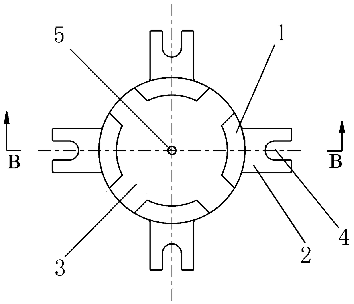
[0042] An embodiment of the mold of the present invention. Such as Figures 1 to 4 As shown, a mold includes a positioning module for positioning the vertical machine base. The positioning module includes an arc-shaped positioning flap 1 extending upward and a horizontal fixing plate 2 connected with the positioning flap. The fixing plate 2 There are fastening holes 4 for fastening with the workbench, and the positioning modules are arranged along the circumferential gap or connected end to end to form a ring to form a mold for concentric assembly with the machine base. In this embodiment, the fixing plate 2 Welded on the outer side of the positioning valve arc and extending radially outward, the fastening hole 4 on the fixing plate 2 is a U-shaped hole, and the opening of the U-shaped hole runs through the end of the corresponding end of the fixing plate 2, when fixing, The two ends of the screw pass through the U-shaped hole and the station hole provided on the workbench re...
Embodiment 2
[0047] Embodiment of the vertical frame processing technology of the present invention. A machining process for a vertical machine base, using the mold in Embodiment 1 to process the vertical machine base.
[0048] In this embodiment, the two ends of the vertical machine base are flange ends and non-flange ends respectively, wherein the non-flange end is the first end face, and the flange end is the second end face, specifically including the following steps:
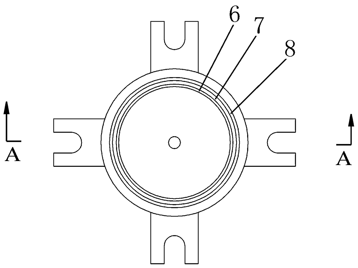
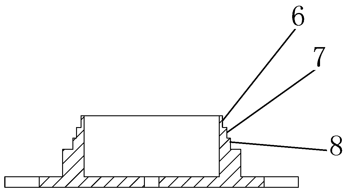
[0049] (1) Fix the mold on the workbench, and install a first boss 6 on the end surface of the tire that matches the size of the non-flange end of the vertical machine base, and the matching gap is 2mm;
[0050] (2) Place the non-flange end of the machine base on the first boss 6 of the mold in step (1), and use the supporting component to support the circumferential direction of the non-flange end to support the inner and outer sides of the flange end of the machine base. Circle datum alignment, leveling with the end ...
Embodiment 3
[0060] Embodiment of the vertical frame processing technology of the present invention. A vertical frame processing technology, using the mold in the first embodiment to carry out turning processing of the vertical frame, such as figure 1 , figure 2 As shown, the two ends of the vertical machine base are respectively flange end and non-flange end, wherein the first end face is a non-flange end, and the second end face is a flange end, which specifically includes the following steps:
[0061] (1) Place the non-flange end of the vertical machine base on the first boss 6 of the mould, use a jack to assist the circumferential direction of the non-flange end, and align with the inner and outer circles of the flange end of the machine base , take the end face of the flange end as the reference leveling, reduce the machining error by aligning and aligning the center of the circle, and then press the corresponding position supported by the jack, and rough the inner circle and end fa...
PUM
 Abstract
Description
Claims
Application Information
 - R&D Engineer
- R&D Manager
- IP Professional
- Industry Leading Data Capabilities
- Powerful AI technology
- Patent DNA Extraction
Browse by: Latest US Patents, China's latest patents, Technical Efficacy Thesaurus, Application Domain, Technology Topic.
© 2024 PatSnap. All rights reserved.Legal|Privacy policy|Modern Slavery Act Transparency Statement|Sitemap