Yarn rod positioning device

A positioning device and yarn rod technology, applied in metal processing, metal processing equipment, manufacturing tools, etc., can solve the problems of yarn rod deformation, affecting automatic yarn loading and unloading, etc., to avoid scratches, prevent contact, and have strong applicability.

Pending Publication Date: 2019-01-01
TAIAN COMPANION MACHINERY
View PDF0 Cites 6 Cited by
  • Summary
  • Abstract
  • Description
  • Claims
  • Application Information

AI Technical Summary

Problems solved by technology

[0004] Aiming at the deficiencies of the prior art, the present invention provides a yarn rod positioning device to solve

Method used


Image

  • Yarn rod positioning device
  • Yarn rod positioning device
  • Yarn rod positioning device

Examples


Example Embodiment

[0024] In order to enable those skilled in the art to better understand the technical solutions of the present invention, the technical solutions in the embodiments of the present invention are described below clearly and completely. Obviously, the described embodiments are only a part of the embodiments of the present invention. Not all examples. Based on the embodiments of the present invention, all other embodiments obtained by those skilled in the art without creative work shall fall within the protection scope of the present invention.
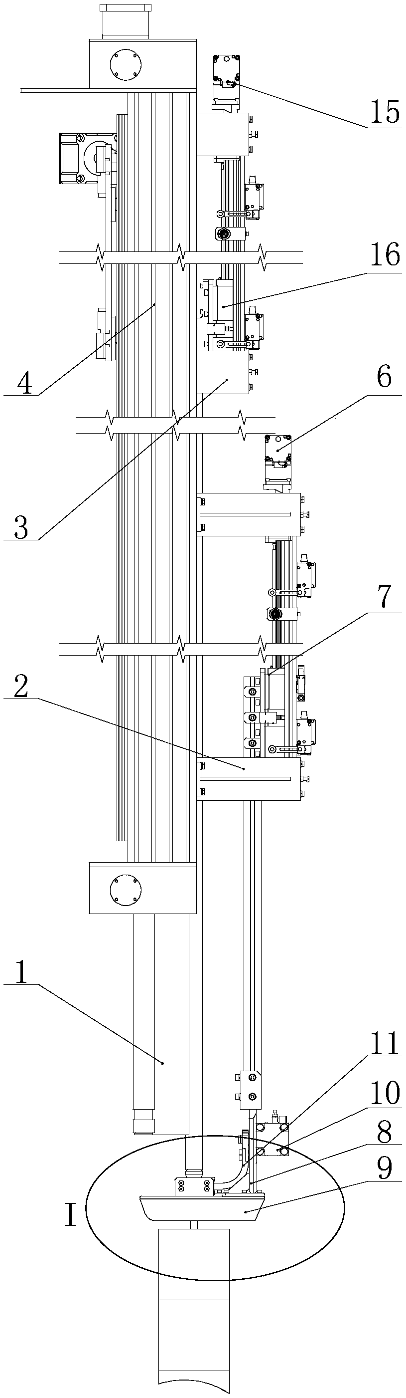
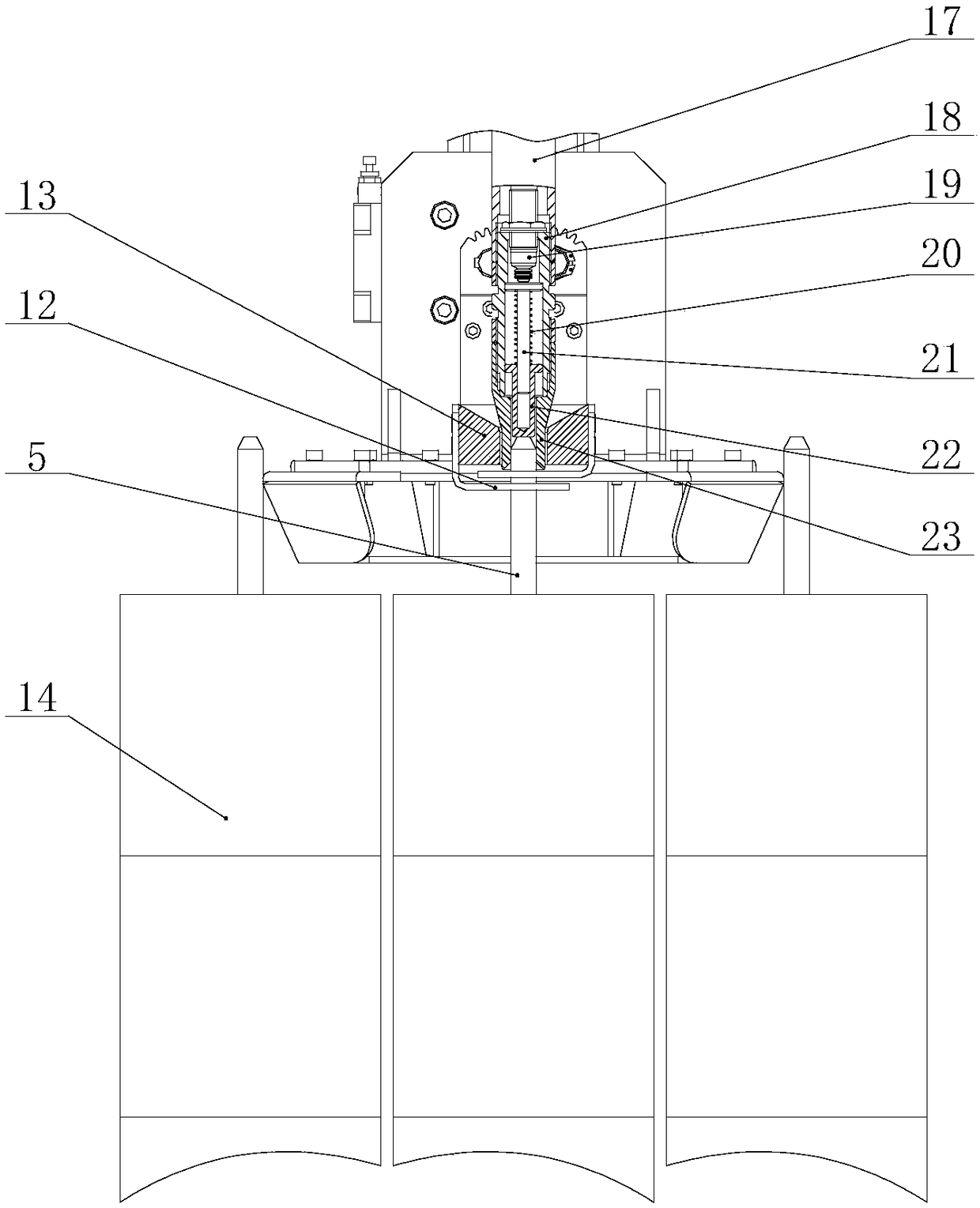
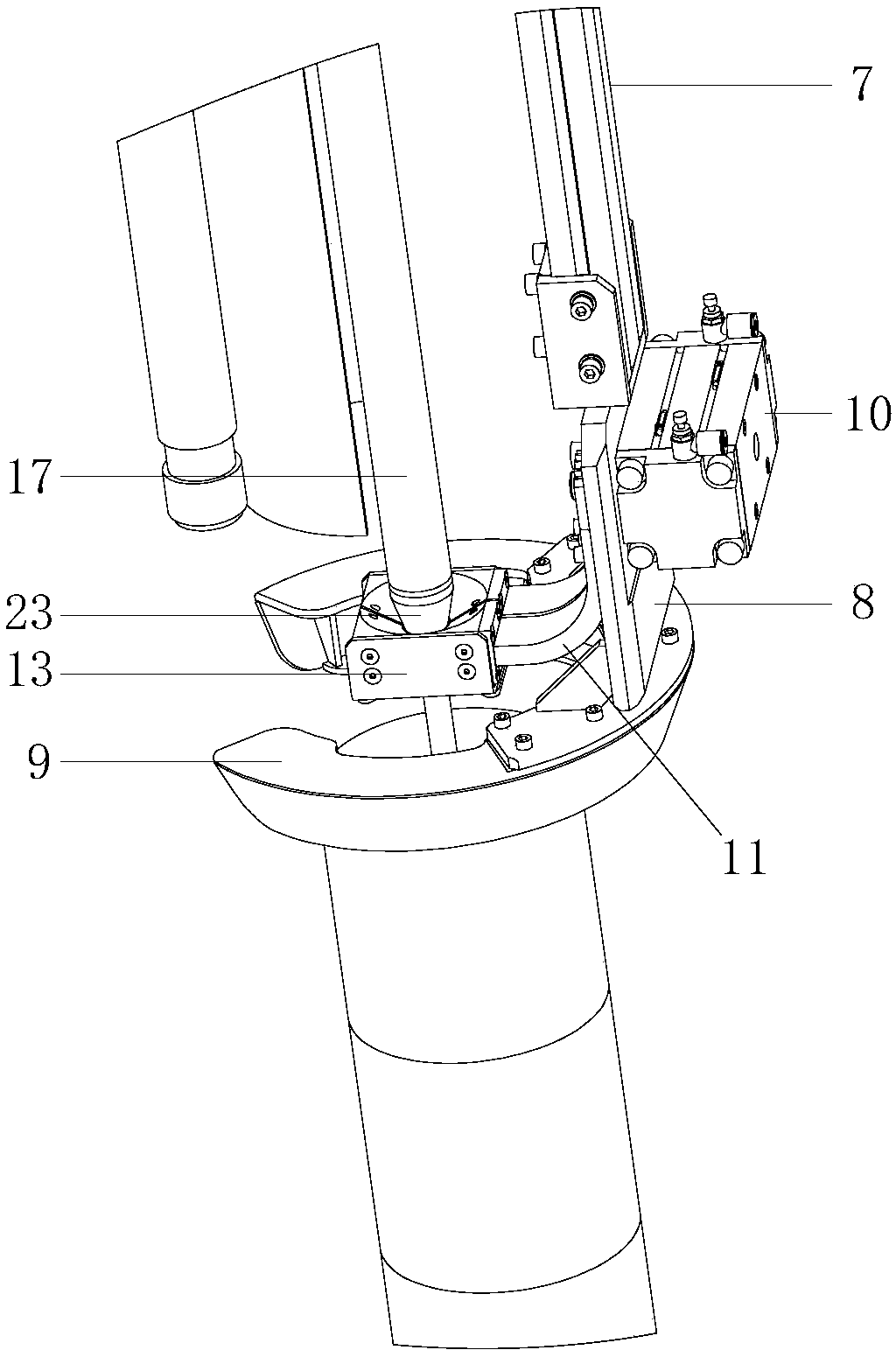
[0025] See Figure 1 to Figure 2 , Which is a schematic structural diagram of a yarn rod positioning device provided by an embodiment of the present invention.

[0026] Such as figure 1 with figure 2 As shown, the yarn rod positioning device is used in a cheese automatic loading and unloading robot, and includes a yarn rod centering assembly and a yarn rod positioning assembly, the yarn rod positioning assembly is located above the yarn rod ...


PUM


Abstract

The invention discloses a yarn rod positioning device for an automatic cheese loading and unloading robot. The yarn rod positioning device comprises a yarn rod strengthening assembly and a yarn rod positioning assembly which are both mounted on a Z-axis frame of the cheese loading and unloading robot; in the yarn rod strengthening assembly, a strengthening drive motor and a strengthening transmission device are used for driving an anti-interference mechanism and a strengthening mechanism to move, interference in yarn rods can be eliminated, and strengthening of the yarn rods required to be positioned can be achieved; and in the yarn rod positioning assembly, a positioning driving motor and a positioning transmission mechanism are utilized for driving a center positioning rod to move, and positioning and feedback of the yarn rods are achieved. The yarn rod positioning device has strong applicability, does not need to replace original yarn cages and yarn rods, can realize automatic positioning of the yarn rods, facilitates automation, is installed on the automatic cheese loading and unloading robot, and can ensure quick and inerrant loading and unloading of cheese by the robot.

Description

technical field [0001] The invention relates to the technical field of printing and dyeing equipment, in particular to a positioning device, in particular to a yarn rod positioning device. Background technique [0002] At present, most cheese dyeing enterprises adopt the method of manual loading and unloading of yarn. This operation method requires a lot of labor, high labor intensity, harsh working environment, and low efficiency, which can no longer meet the needs of the printing and dyeing industry to realize intelligence; therefore, Automation of the yarn loading and unloading process has become a trend. [0003] Because the old sarong does not meet the requirements of automatic loading and unloading, the rigidity of the yarn rod on the sarong is generally poor. After a long time of manual loading and unloading, the yarn rod is seriously deformed, and the verticality between the yarn rod and the sarong base can no longer meet the requirements of automatic loading and unl...

Claims


Application Information

Patent Timeline
IPC IPC(8): B23P19/00
CPCB23P19/00
Inventor 吴士斌赵磊陈振唐李明刚
Owner TAIAN COMPANION MACHINERY
Why Eureka
Try Eureka