Air preparation device for use in an air flow path of an air-conditioning system in a mobile device

A technology for air handling devices and air conditioning systems, applied in air conditioning systems, air handling equipment, mechanical equipment, etc., can solve the problems of air turbulence, increase flow noise, interfere with air guidance, etc., and achieve the effect of reducing noise

Inactive Publication Date: 2019-01-01
CARL FREUDENBERG KG
View PDF9 Cites 0 Cited by
  • Summary
  • Abstract
  • Description
  • Claims
  • Application Information

AI Technical Summary

Problems solved by technology

Such scent cartridges interfere with the air guidance, generate undesired air turbulence and may likewise lead to increased flow noise
[0006] In general, the aromatization of the co

Method used


Image

  • Air preparation device for use in an air flow path of an air-conditioning system in a mobile device
  • Air preparation device for use in an air flow path of an air-conditioning system in a mobile device
  • Air preparation device for use in an air flow path of an air-conditioning system in a mobile device

Examples


Embodiment Construction

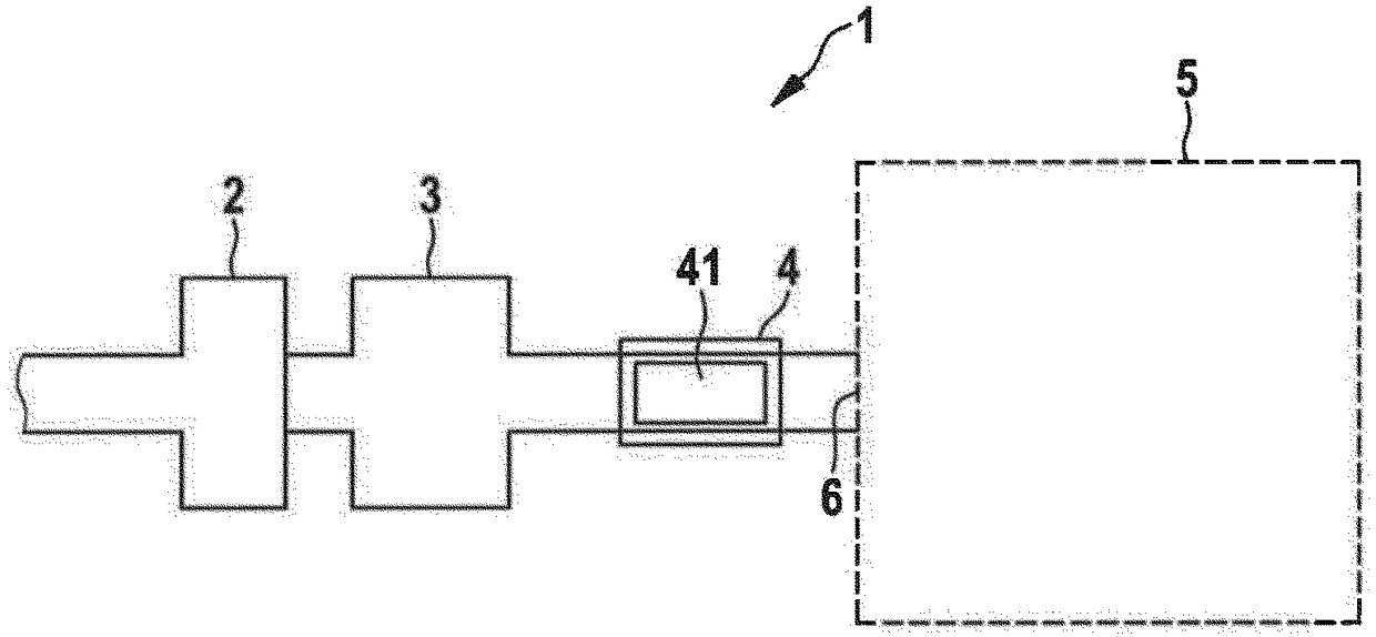
[0028] figure 1 An air conditioning system 1 for an interior, for example of a motor vehicle or the like, is shown schematically. The air conditioning system 1 comprises ventilation means 2 to draw in fresh air from the surrounding environment and provide an air flow which then passes through a heat exchanger 3 to cool or heat the conditioned air.

[0029] Downstream of the heat exchanger 3 , an air treatment device 4 is arranged in the air flow before it enters the inner chamber 5 . In particular, the air treatment device 4 is arranged directly on the air outlet 6 or as close as possible in the interior 5 to the air outlet 6 and can be arranged exchangeably in the air flow.

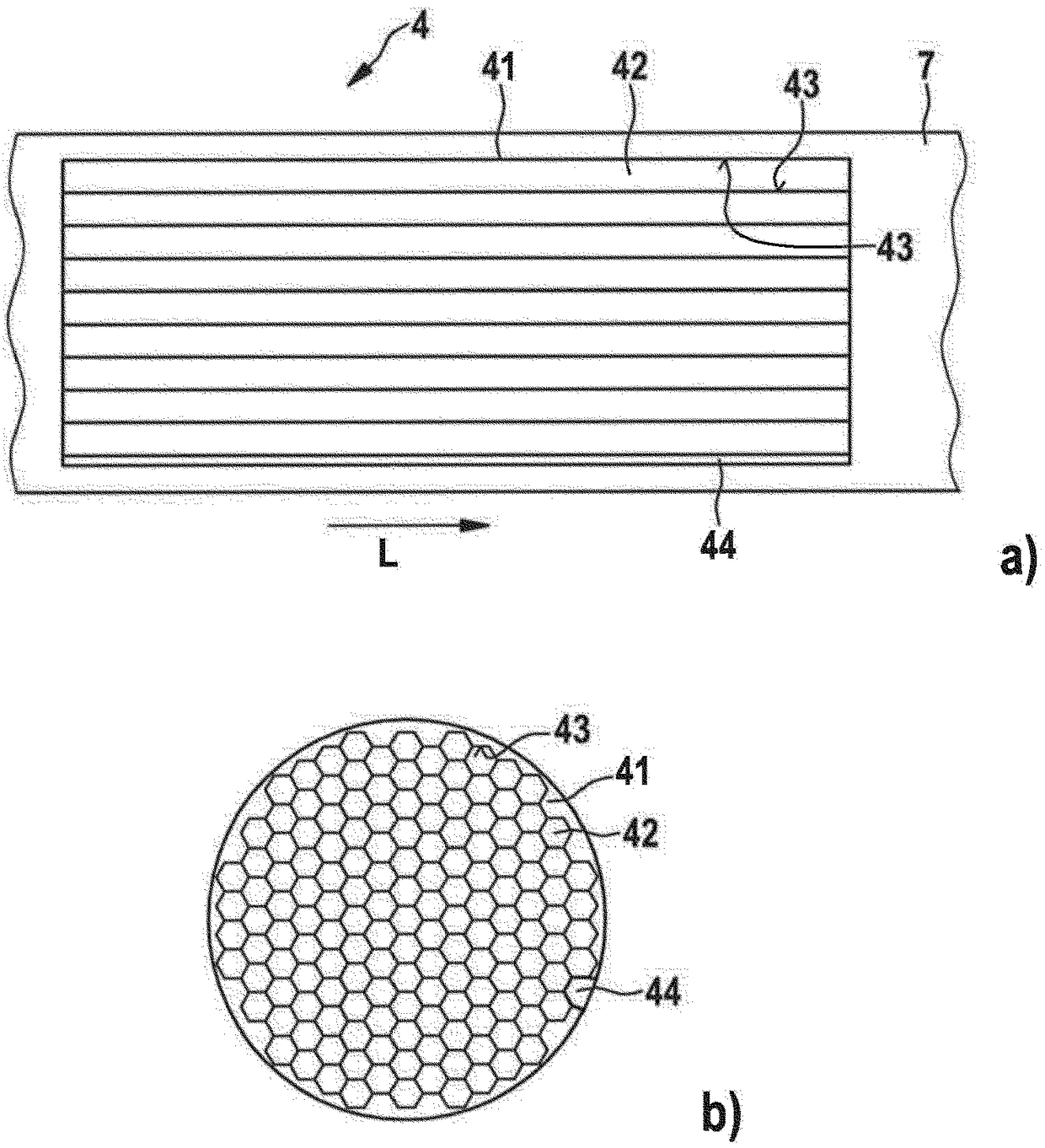
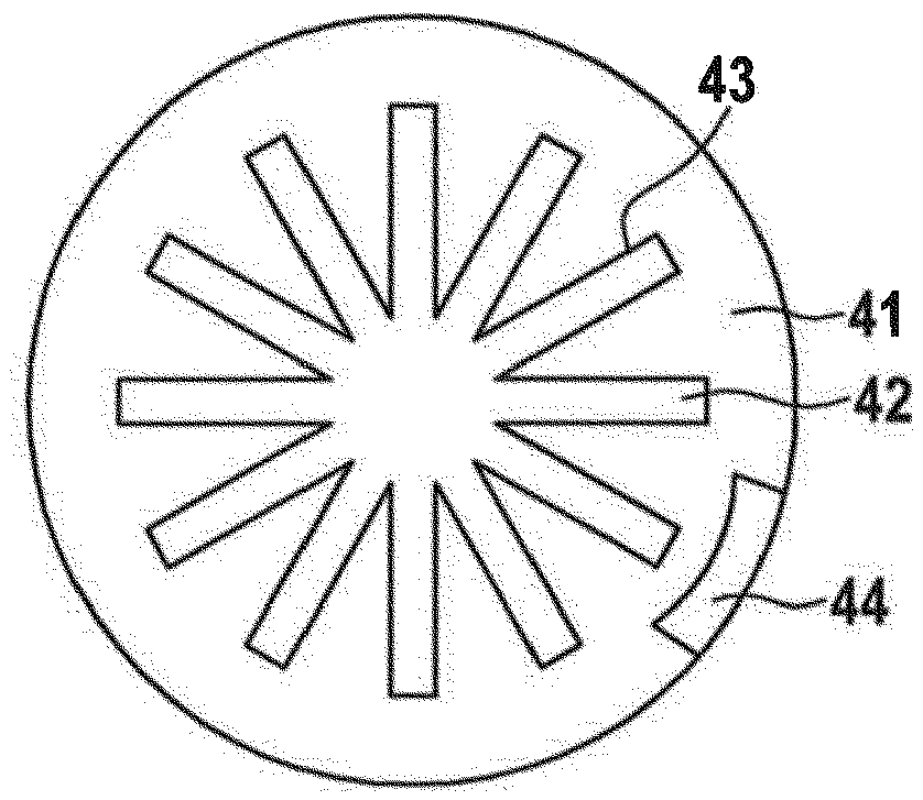
[0030] figure 2 a and 2b show various views of an exemplary air treatment device 4 . exist figure 2 In a is shown a sectional view along the longitudinal direction L, which corresponds to the flow direction of the conditioned air. figure 2 b shows the corresponding cross-sectional view. figure ...


PUM


Abstract

The present invention relates to an air preparation device (4) of use in an air flow path of an air-conditioning system (1) in a mobile device. The air preparation device includes treatment elements (41, 51) having one or more passages (42, 53 and 65) extending in part or completely in a flow direction. The passages (42, 53 and 65) include fragrancing faces (43) that extend in the flow direction and are designed to release one or more fragrant substances into an airflow that is flowing through.

Description

technical field [0001] The invention relates to an air treatment device for being arranged in an air flow for air-conditioning an interior, in particular a mobile device, such as the interior of a motor vehicle. Background technique [0002] An air handling unit may be used to provide fragrance to conditioned air prior to introducing it into the interior. Frequently, air treatment devices of this type are formed with a non-woven fabric impregnated with fragrance substances arranged in the flow path. The ventilation device conveys an air flow through the fleece in the direction of the inner chamber. [0003] The volume of nonwovens impregnated with fragrance substances is very limited, so that the fragrance effect lasts only for a short time. It is also not possible to adjust the intensity of flavoring with this system. As a result, the flavoring effect decreases significantly over time. [0004] Furthermore, such air treatment devices create a flow resistance, due to whi...

Claims


Application Information

Patent Timeline
IPC IPC(8): B60H3/00
CPCB60H3/0028B60H2003/005B60H2003/0064F24F3/12B60H3/0021B60H2003/0042F24F8/50B01D39/14B01D46/42A61L9/03A61L9/012A61L2209/16A61L2209/134
Inventor U·施塔尔V·布劳恩林
Owner CARL FREUDENBERG KG
Why Eureka
Try Eureka